M&K Junction Railroad

M&K Junction Railroad
Another train of eastbound coal crosses the Cheat River

Thursday, May 31, 2012

Roster Shot


Some time back, I wrote a post about an old school "box of sticks" boxcar kit that I had nearing completion after starting it more than 20 years previous (see Oldie But Goodie?). Well it's taken a couple of more years to finally get it done but, as you can see, it's on the layout, painted and operational. 

There was a great sense of satisfaction in finally finishing this project.  This is in spite of the fact that I could have purchased an Atlas O Trainman model of essentially the same prototype for about $42, taken it out of the box, put it on the rails and have been done with it.  Arguably my model is inferior to the Trainman RTR.  My model is missing a few details (most notably some of the grabs and the brake staff and wheel, which I will remedy); however, my brake rigging (borrowed from an Intermountain kit) is freestanding rather than the cast on blobs of the Trainman.

Where a kit like this really shines is in confidence building.  It probably took me as long or longer to build this kit as it would have taken to scratch build it.  However, faced with the terra incognita of scratch building this prototype, I might never have started.  The kit gave me a road map, however sketchy, for turning a box of sticks into a boxcar; and the confidence that someone, somewhere at some time thought that this could be done, therefore I should be able to do it as well.

It's a shame that these types of kits are no longer available as I have found that they can be great builders of proficiency.  But wooden kits have long been relegated to ancient history and the more recent cast-resin kits are on their way out as the makers of resin kits retire. 

Speaking of cast resin, I have a bunch of these kits and one is under construction and is next up for completion after I finish a Red Caboose tank car kit.  Stay tuned.

Monday, May 7, 2012

On Grades and Helpers

For starters, here's a quick video that I shot entitled "The Cheat River Grade Helper":


After shooting this video, I realized that I should do something about the bare backdrop on the Cheat River Grade. I cannot make a photo backdrop right now, but maybe I can at least paint the backdrop a sky blue.

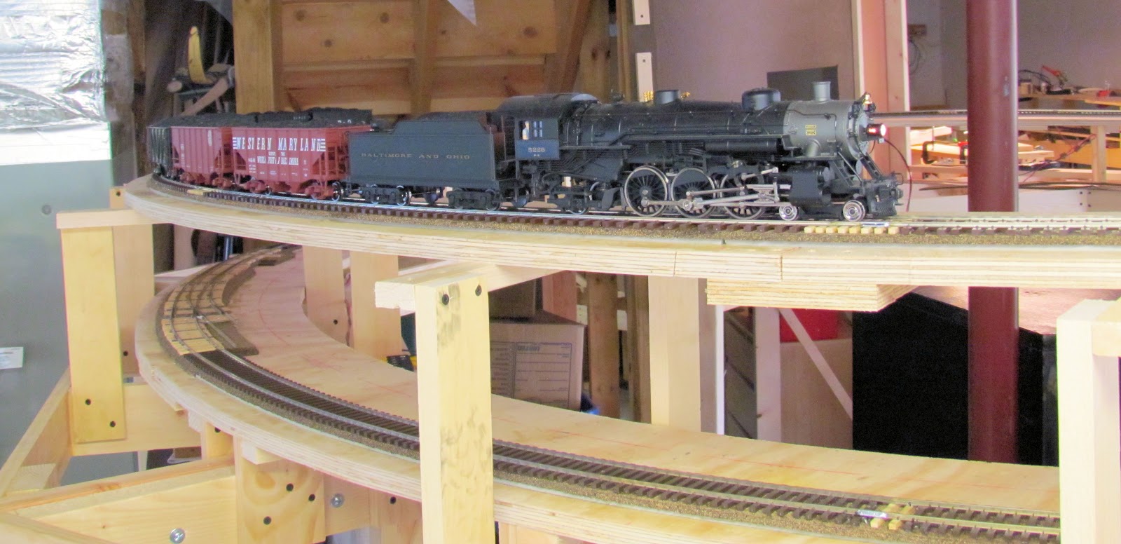
 In my previous post, I remarked on the necessity for using helpers (or more head-end power) on the Cheat River Grade. This grade is 2% and nearly matches the prototype. In building my model railroad I have used Charles Roberts' book: "West End" as my "bible". My experience with needing helpers on the grade caused me to review the section in Roberts' book on equipment. Roberts compiled statistics on how many cars the prototype could pull up the grades. He used an interesting metric, number of cars puled per powered axle. Using this as a metric eliminates the differences in wheel diameter, steam vs. diesel, etc. What he found was that over the period of time from 1850 to 1991, the B&O could haul between 2.1 and 2.4 cars per powered axle up the grades. That is essentially the same result that I have obtained after testing with several model steam and diesel locomotives; between 2 and 2.5 cars per powered axle (and the latter number with a lot of wheel slip).

I believe that John Armstrong observed in one of his books on layout design that given needle-point axles model locomotives will pull more on the grades and less on the flats than prototype locomotives. He further observed that to create a helper grade that would seriously challenge model locos, 3% was about right.  I would certainly never dispute John Armstrong, but in my particular case the grades and, especially, for the combination of curves and grades, 2% seems to be about right.

It will help that most of the hoppers going up the Cheat River Grade will be empty (unlike the video above, which was just for fun) and I can arrange that most of those will be plastic models.  But the loaded hoppers coming down the Cheat will have to go up Cranberry Grade, also 2%; and these hoppers will be loaded.

During the period 1949-1952, the B&O used A-B-B-A sets of F7 diesels as pushers to help trains headed by, typically, a 2-8-8-4 articulated up both of these grades.  Assorted 2-8-8-0s and Q4 2-8-2s (as seen in the video above) were also used as pushers.  I intended to use A-A sets of diesels and Q4s as pushers.  The eight powered axles on the diesel pushers would be about 16 cars capacity, that should be OK.  The four powered axles on the Q4 would only be 8 car capacity - that might not be enough.  Matching the pusher to the train length could make the operating game more interesting.

Sunday, April 29, 2012

Open House Recap

On Saturday April 28 I held my third open house. Nine people attended and, I believe, that a good time was had by all. Five of the nine were new guests. Two came down from Gettysburg, PA and one came up from the Richmond, VA area. I do live out in the sticks and getting here is a bit of a chore which, unfortunately, tends to keep turnout down.

On Tuesday the 24th, I stopped new work on the layout. I could have laid about another 10-15 feet of track, but it became obvious that I would not be able to connect the two ends of the mainline by Saturday; so I decided not to push it any further and begin the cleanup of the layout and check-out of equipment prior to Saturday.

It's a good thing that I did. I have only one lighting circuit in the basement.  There are a lot of lights in the basement.  During construction, I usually have all of the lights over the aisles on and only those lights over the layout in the area where I am working.  I was not sure that if all of the lights were on at once, it would not pop the circuit breaker.  The total load is not easily calculated as you can add up the wattage of all of the florescent tubes, but it's not easy to determine the current consumed by the electronic ballasts.  I suspected that I was near the limits.  Friday night I deliberately turned on all of the lights and waited to see what would happen.  The lights stayed on and, after a while, I forgot about it and went on testing rolling stock.  Unexpectedly, I was involuntarily plunged into "night operations" as the breaker opened (the loco headlights and control panel lights were cool!).  The solution, at least temporarily, was to turn off all of the aisle lights when all of the layout lights are on.  Since I still have more layout lights to install, long-term, I'll have to move some lights to another circuit.

I resolved a tight-gauge problem with a curved turnout that I laid in one of the helix tracks to make up for the over sized scissors crossover (Unfortunately due to time pressure I did not document the construction of this turnout, but let me say that it runs very well).

With insufficient time to thoroughly wring-out the track on the helix, I decided to make up two trains to run up the helix and check out these trains for proper operation on the helix.  One train was a mixed freight made up of 8 plastic cars plus caboose and pulled by a plastic Weaver RS-3 (still in Rock Island paint).  The other was a 7 (later 8) car train of coal hoppers made up of five die-cast hoppers and three plastic hoppers (filled with coal loads).  This latter train was pulled by a die-cast Weaver Pacific steamer.

Now that I had a lot more track to run trains on, these trains began to tax the capabilities of the locomotives.  As the trains pulled the grade approaching the helix and, especially, once the trains were entirely on the curve of the helix, the motors were really straining, as indicated by their noise.  This was particularly noticeable with the BEMF decoder in the steamer, it was really pulsing the motor.

There was some minor wheel slip on the coal train with 7 cars (5 of which were heavy die-cast), when the 8th car was added Saturday morning, wheel slip was very noticeable.  Engineers had to actually work this train using techniques like making a "run for the hill" and managing the throttle to minimize wheel slip.  Now I had an answer for a long-standing question of mine, would the grades be sufficient to actually require helpers?  The answer, of course, is yes.  I will add some weight to all of my locomotives and, once I have helpers running, no "five-finger assists" will be allowed.

The old-hand attendees remarked on how much progress had been made since September's open house.  New guests had a lot of questions about the layout's design and construction.

Saturday was gloomy and overcast here in Northern VA, so the planned cook-out was scrubbed and we had an indoor sandwich buffet.  My good wife made several dozen (must have been 4-5 dozen) homemade chocolate chip cookies (her best batch yet!) and they were almost all eaten during the course of the day.

After lunch ended a few stayed on and the topic turned almost entirely to operations.  I outlined my concept of operations, based on actual B&O helper operations out of M&K junction including a couple of ideas I had to make the game slightly more realistic.  I believe that my concepts were well-received and, since one of the guests was an actual brakeman, I consider that high praise.

No group picture this time since we were not outside to take one.  But while the layout is reasonably presentable, I took the following pictures as a tour for those who could not attend.


M&K Junction (still unfinished) above.


On Cranberry Grade (above).


The curve through Rowlesburg, WV (no, the track is not actually super elevated, I did that with the camera).


Further up Cheat River Grade (done in the style of the railroad publicity photos of old)


Entering the helix.


Climbing the helix.


About to penetrate the backdrop


Through the backdrop. Entrance to the helix is below. (this view will eventually be covered by scenery)


Second turn of the helix.


End of track on the helix.

Friday night before the open house I put together a movie.  I must apologize for the quality of the sound.  The sound is from a older Soundtraxx DSX decoder recorded separately and dubbed onto the video; therefore synchronization is not the best.  Also I did not turn off the air pump, which comes on at inappropriate times.  But you can always turn off the sound; it's too loud too, so you'll probably want to turn it down in any event..  Click in the play bar to turn on HD, if you have the computer and connection to support it.


Wednesday, April 18, 2012

The Hole In The Wall

Well, not in the wall precisely, but in the backdrop. For some time I've known that the second turn of the helix would have to pass through the backdrop on the Cheat River Grade. I've been putting off the job of cutting the hole, but it can be put off no longer.

One reason for dreading this task is it will intrude on what is a nice alcove at the end of the Cheat River Grade. I will be able to camouflage it, and do so in a way that is true to the prototype entrance to the Kingwood Tunnel. The other reason for putting this off was the actual job of how to measure and cut the opening.

The helix sub roadbed has been built to a point just short of the backside of the backdrop for some time while I figured out a way to accurately measure where it will penetrate the backdrop. I solved this problem by clamping a laser pointer to the sub-roadbed and marking the backdrop where the pointer indicated. From that datum, I measured out the dimensions on the opening. This worked well and I only had to widen the opening by about an inch to make everything fit and align.

Here's what the opening looked like just after cutting.


This is the backside of the backdrop and the hole opens into the alcove at the top of the Cheat River Grade. The next shot shows the hole from inside the alcove.


That's the end on the Cheat River Grade in the lower foreground; one track (of two) is laid and enters the helix to the right.

Here's the sub-roadbed being extended through the backside of the backdrop.


And from inside the alcove:


From this angle you can see how the track enters the helix at the bottom; the second turn of the helix is, of course, penetrating the backdrop. You can also see how the track snakes between the lolly column (the red column), and various parts of the support for the basement stairs. A lot of track is squeezed in here on two levels.

Speaking of the helix, here's one track entering the helix.


Here's that same track as it begins to wind it's way up the first level of the helix (the second level is yet to be constructed at this point).


More helix to build and a lot of track to lay before the 28th of April.

Friday, April 6, 2012

Setback!

I've been able to get a lot accomplished this week, although I have had a layout-related disappointment.

I rewired and rehung the lights on the Cheat River Grade and the new arrangement is much improved.

Unfortunately, the scissors crossover that I sweated over building (literally and figuratively) for the last several weeks did not fit where intended. I should have laid this out in CAD; I even should have thought through the geometry before building it. I can see now that it will require a curved crossover to fit the space. I believe that given enough time I could build a curved scissors crossover, but it would not be complete in time for my next open house; so I will build it as two single curved crossovers. To do so I have just ordered more code 148 rail. However, this setback practically assures that I will not have the helix finished by the date of the open house.

In the meantime, I have begun laying the track on the helix, over where the scissors crossover would have been and it looks like this:


The roadbed in the foreground is on the helix and you are looking towards the Cheat River Grade in the illuminated space towards the rear. The roadbed is dual layer cork on top of camper (topper) tape. The track ducks under the basement stairs in this location. We don't let physical obstacles deter us!

Saturday, March 31, 2012

The Scissors Crossover

Before track can be laid on the Mother of All Helices (MOAH) I had to build a scissors crossover. Since the helix is designed to be serial storage for trains, the crossover is at the entrance of the helix and will allow me to store trains from either direction on either track of the helix. It will also allow trains into and out of hidden staging which will have a connection on the inner track on the lower level of the helix.

To this end, I had built four Fast Tracks jig-built turnouts (2 right hand and 2 left hand). I intended to build these into the crossover. Unfortunately, I could find no good information on building a scissors crossover. Fast Tracks had printable templates for building one in HO or smaller scales, but they were not available in O scale; and they were for a much tighter track center spacing than I was using so they could not be enlarged to equivalent O scale.

The NMRA had no data on building one using the #6 turnouts that I had on hand. Particularly I wanted to know the degree of the crossing in the middle as a function of the turnout number and the track center spacing.

Paul Mallery's "Trackwork Handbook" had instructions for scratch building a simple crossing and it was of some help.

I guess that I could have calculated the angle of the crossing using geometry had I put my mind to it. Instead, for better or for worse, I decided to wing it and improvise as I went.

So I started to lay out the crossover on the back of my 2x4 ceiling tile where I build most of my scratch built track. The two left-hand turnouts were positioned first as these form the facing-point crossover which will be the most often used route through the crossover. The turnouts had been built with extra-long rails on the diverging routes and I joined these to form a continuous route through the crossover.

Here's what that looked like:

IMG_0769_edited

IMG_0770_edited

Next, it was time to start fitting the right hand turnouts. The straight legs of the turnouts were temporarily joined with rail while the diverging leg was butted against the left hand crossover. These pictures show it best.

IMG_0771_edited

IMG_0772_edited

To keep the straight routes in line and in gauge, I used Fast Tracks "Sweep Sticks". I had what I thought was a brilliant idea to cut one of the sweep sticks into a tool that would hold the intersecting rails in gauge as well as to the proper angle while they were being soldered to the previously laid crossover. The next photo shows how I used sweep sticks.

IMG_0773_edited

The angle-cut sweep stick did not work out as well as I had planned. I did not have enough hands to hold the rail tight against the sweep stick while wielding the soldering iron and the solder. However it worked well enough to keep the track just within tolerance by the NMRA gauge.

Once the first right hand turnout was soldered in place the problem of how to align the turnout on the opposite side arose. This time I had better luck with improvising a tool. I made a tool out of 3/4" x 1/8" aluminum, notched to fit over the in-place rails and which would hold the off-side turnout rail in alignment with the turnout already soldered in place.

IMG_0793_edited

IMG_0800_edited

The detail shot shows how the tool is held in place with wooden clothes pins with their handles turned around and end-for-end so that the straight legs are pinching the tool to the rail. It's important that a tool like this be used on the gauge side of the rail and not on the off-side.

The tool, with a lot more clothes pins, was also used to align the rails in the center of the diamond:

IMG_0809_edited

Here, the two running rails in the center of the diamond are aligned and soldered in place:

IMG_0816_edited

Here's the scissors crossover with all running rails in place:

IMG_0822_edited

Now came the really tedious part - the guard rails. The guard rails will have to have part of their base removed to fit against the running rails; and where their ends butt against the running rails they will have to be filed to an angle as well as having the base relieved to fit snug against the running rail.

Before the guard rails could be fitted the flange ways had to be filed through the running rails. I tried, without success, to use a Dremel tool for this purpose. Even though I have a cutter that it the exact size for an O Scale flange way, I could not hold and guide the tool accurately enough to cut a good flange way. In addition the tool had a tendency to catch on the rail and become uncontrollable.

During the fitting of the guard rails and the filing of the flangeways, I ran into a curious problem. After checking the work with the NMRA gauge, I would run a truck through. This particular truck was removed form a car where I had replaced all of the wheel sets with Precision Scale wheel sets. Oftentimes one wheel set on the truck would have no problem going through, but the other would hang, usually catching the back of the wheel set on the guardrail or in the flange way. For the longest time I did not question what are supposed to be high-quality wheel sets, and I did a lot of extra filing to get the thing to pass through.

Finally frustrated with the amount of filing that I was doing, I checked the wheel sets. Sure enough one wheel set on the truck was wide-gauge. So I got the other truck from the original car and start using it - and the problem persisted! This time I checked the wheel sets early and one wheel set on this truck was wide too! So out of four wheel sets, from a reputable company, two were out of gauge. Just goes to show, take nothing for granted.

Here are pictures of the completed scissors crossover.

IMG_0835_edited

IMG_0840_edited

IMG_0836_edited

IMG_0831_edited

IMG_0827_edited

Placement of the PC ties was ad hoc and did not follow any pattern. Fortunately, this scissors crossover will be hidden from view (but still easily accessible) inside the helix; so the fact that it's not competition quality is not an issue. Still it's a shame that no one will admire my handiwork.

I will have to build another one of these for the top end of the helix, to get re-routed trains back on their proper tracks. But that's a job for April.

Friday, March 2, 2012

It's Itsy-Bitsy

I've finally finished a project that I've been thinking about since 2007, namely, creating a scale B&O Color Position Light (CPL) dwarf signal. What's the big deal, you ask? It's to exact scale and it's itsy-bitsy.

The story starts at the 2007 O Scale National Convention. I attended a clinic by a gentleman who was using 3D Computer Aided Design (CAD) and a jeweler's 3D wax printer to create O Scale parts. He would design a part in the CAD program, send it to the wax printer which would print a copy of the design in wax. The wax model would then be used to make a rubber mold, the mold would make more wax copies which were then used in a conventional lost-wax process to produce the final parts in brass.

While this sounds complicated it was, for its time, an inexpensive and fairly simple way to get to finished parts if you needed more than one copy.

At the time I had been looking into various 3D printing processes concentrating on stereo lithography (SLA), but the costs of those machines were astronomical and having models produced on them was far too expensive, even for one piece; so the wax printer/lost wax process was promising.

Soon after the convention I settled on the B&O dwarf signal as the model that I wanted to produce in O scale. It had never been done to scale; MTH (and, I believe, Right-o-Way) having produced grossly over sized versions for the 3-rail O gauge market. Also, I had the plans for the General Railway Signal Type 'VA' B&O CPL dwarf signal so that would make it easier.

Here's a picture of the prototype.


This dwarf has two additional markers and a sign on top, but the basic signal is the lower eight lights.

The CPL dwarf is a difficult signal to model. Eight lamps, each with visor, on a small target would be difficult and expensive to produce by conventional machining; even to build a single master for reproduction by casting. Many 3D printing processes, like fused deposition modeling (FDM), are too coarse to produce a small, finely detailed model.

In 2009 I took a job where we use 3D printing (out shopped) to check designs before we commit them to production. I had a chance to sample several different 3D printing processes as well as get some exposure to 3D CAD. Now I had access to the tools and some people who could help me out.

Here's what the 3D model of the basic CPL dwarf signal looks like:


This model is somewhat simplified. The nuts and bolts on the case are not reproduced; nor are the ribs on the backside of the case back; nor are the edges of the case rounded. As it turns out, none of these are visible at normal viewing distances.

I still needed to find a supplier that could produce the models without charging $80-100 for each one. Enter Shapeways. I'm not the first modeler to discover Shapeways 3D printing service. Their service is unique; they offer several different 3D printing processes, they offer worldwide shipping, their prices are reasonable and they are modeler-friendly.

I designed the model to use the full capabilities of Shapeway's "Frosted Ultra Detail" (FUD) material which could hold the smallest features out of all of Shapeway's processes. FUD is a 3D printing process called 'PolyJet', which prints a part using a UV-cured plastic shot from a multi-nozzle print head much like your inkjet printer prints. The signal's shell, which is hollow to allow for illumination, is made to the minimum thickness allowed by the process. With some trepidation as to how they would appear, I made the visors a little thicker than the minimum for strength.

Since the model was done on a heavy-duty 3D CAD program (Solid Works) it passed all of Shapeway's tests for printability. After I uploaded the model to Shapeways, I discovered, to my delight, that the model could be produced for well under $10 (US); so I ordered one.

When it arrived, it struck me just how tiny this thing is. It's so small that I am convinced that it could not have been produced to scale, with scale-sized visors, by most other process, especially casting. Here's what the model looks like.


The model is on the dining room table's tablecloth and that's the weave of the fabric that you can see. This gives you some idea of the size of this dwarf. I'm really happy with the way the visors came out. They are 20 thousandths of an inch (less than one inch in O scale) and although that is thicker than the prototype, you cannot tell from looking at it.

Here's a picture on the layout:


That's an O scale E7 in the background. The O scale figure is 1.43" tall (36.43 mm).

I have made some changes to the back cover of the signal, which is a separate piece, and I have another batch on order. When those arrive I'll experiment with painting (Shapeways could not advise me on compatibility of FUD with paints) and illuminating. I'm sure that this signal can be illuminated with 'chip' LEDs; but that will require me to design and lay out a circuit board, which will take a while.