
Here's a video of a loco running on the layout. No good reason for filming this. Currently, this loco is being repainted for the B&O.
Wednesday, November 11, 2009
Tuesday, November 10, 2009
To The West!
Now was the time to build to the west (by the B&O timetable) out of M&K Junction, through the town of Rowlesburg, WV and up the Cheat River grade. This section of the basement is in front of the water heater and well tank; the lower left hand side of the track plan (see Jul. 24, 2009 posting). It will also pass by my workbench.
Here's what it looks like leaving the Cheat River Bridge - what a lot of clutter!

More benchwork sections had to be built as can be seen here:

First is the view towards the water heater and next is the view towards the workbench:

The section beside the water heater will be filled in as well to support either a coal prep plant or the Alpha Portland Cement plant that is across the Cheat River in Manheim, WV on the M&K sub of the B&O. These sections of benchwork can be seen next to the water heater in this photo:

These sections are designed to be removed in the eventuality of the water heater needing replacement, therefore they have no main track on them. If the water heater goes these sections will be removed, the water heater can then be tilted over and laid down to the floor and rolled out from under the main benchwork.

This last photo shows the subroadbed cut to match the curve of the track in this location. Ordinarily I would cut a similar curve in the outer edge of the subroadbed, but this location will have the town of Rowlesburg, WV on it so I have left it square.
2008 O scale National
Here's a collection of short videos that I took at the 2008 O Scale National Convention. The first video is hosted off-site and may not play smoothly and may require a high bandwidth Internet connection. I suggest that you click the play button and then pause it to allow the entire video to download. The second video is smaller and is hosted on Blogger and plays smoothly. Use this one on a slow internet connection. Both videos are the same.
Enjoy
Enjoy
Lenz Decoder Performance
I installed a Lenz Gold Maxi decoder in an O-Scale Weaver die-cast USRA Light Pacific. In spite of the loco's cheap Mabuchi RS-385 motor and simple gearing the results are pleasing (to me anyway). I have timed the loco at speed step 1 to take 49-50 seconds to travel one foot, which calculates to 2/3 scale mile per hour. Not too shabby. I did nothing to the decoder except install it, I did not program start voltage, speed tables, etc., this is as it comes. BEMF was turned on from the factory.
Here is a video of its performance:
In the first segment you can see the loco at speed step 1 traveling past a 1 foot ruler propped up beyond the track. The oblique angle makes accurate timing impossible, but you can see that it takes some time.
In the second segment, I show a close-up of the valve motion demonstrating the smoothness of the motor control.
The Lenz decoders have something called 'yard mode' which cuts loco speed in half and can be turned on and off using F3 (mappable). In the third segment I start the loco at speed step 7, engage yard mode part way through the segment, then disengage it.
Finally, the last segment shows the loco coupling to a converted K-Line die cast hopper at speed step one - no slam-bang here. My miniature brakemen will be perfectly safe.
I probably could improve low speed performance with some tinkering with the decoder settings, but as it is this is a vast improvement from the straight DC performance.
The Cheat River Gets A Backdrop
In 2007 I made my second trip to Rowlesburg, WV the location of M&K Junction on the former B&O, now CSX. While there I took lots of digital pictures for reference and, potentially, for creating backdrops for my model railroad. Among the pictures that I took were a series of shots from the highway bridge over the Cheat River looking south (as would be seen standing in the aisle looking at the Cheat River bridge on my layout) and facing north (which is facing the opposite direction from the scene on my layout).
Some of these photos were a series of overlapping shots intended to be stitched together using photo stitch software. When I did that for the Cheat River shots, it was clear that the view southward, the way it should look for my model railroad, was scenically uninteresting for use as a backdrop. The view northward, however, was really great. So with some reluctance to abandon authenticity, I decided to work with the northward-looking view.
Upon studying what was now a Cheat River photo mural, I saw that the terrain rose to the right in the photo and fell off to the left. This was exactly the opposite of what was needed to fit the intended scenery of my layout. On thinking about this now, it's not surprising that the view in the opposite direction would be flipped left-to-right.
The solution was obvious, flip the mural in Photoshop. While I was in Photoshop, I also eliminated a couple of distracting parts of the picture (mostly roads) until I was satisfied. Is a photo mural of the Cheat River looking the wrong way, flipped left-to-right and with elements edited out still a representation of the Cheat River? I don't know, but I'm happy with the results.
But I was not done yet. Three, 6-megapixel photos stitched together doses not a backdrop make. I had to expand a picture that would have printed out, at best, 11" x 24" into a wall-sized print. To accomplish this task I used Gimp, a open source (freeware) photo editor almost as powerful as Photoshop. This was a multi-step process that will be the subject of a future post; but suffice it to say that it required many hours on a dual-core laptop and, eventually, a used Dell workstation purchased off of E-bay to generate a 33" x 72", 300 dpi, 70 Mb file.
Printing this enormous file was another problem. I had access to a HP DesignJet 4000 large format printer. After literally dozens of attempts that either did not print out, or printed out at the original 11" x 24" size, I finally got the 33" x 72" print I was looking for; to this day I don't know how I did it.
I mounted the print to 1" blue foam board, put it behind the still-unfinished bridge over the unfinished Cheat River on the layout, stood back and shrugged my shoulders. Surrounded by all of the unfinished plywood and no other scenery it didn't look like much.
And that's the way it stayed for a few months; until one day I was down in the basement with my camera and, on a whim, put a colorful reefer on the bridge and snapped a photograph. By chance the shot was more or less looking down the river in the backdrop and not flat-on to the bridge and, although the shot was not perfect, the sight of it on the camera's screen made me say WOW! Here is that first photo:
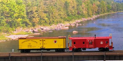

The first picture is nice, but the second one, with the models in the exact same location on the bridge, is spectacular. By controlling the viewpoint and the zoom, the camera turns a scene that is not very impressive in person into a first-rate photo location.

Some of these photos were a series of overlapping shots intended to be stitched together using photo stitch software. When I did that for the Cheat River shots, it was clear that the view southward, the way it should look for my model railroad, was scenically uninteresting for use as a backdrop. The view northward, however, was really great. So with some reluctance to abandon authenticity, I decided to work with the northward-looking view.
Upon studying what was now a Cheat River photo mural, I saw that the terrain rose to the right in the photo and fell off to the left. This was exactly the opposite of what was needed to fit the intended scenery of my layout. On thinking about this now, it's not surprising that the view in the opposite direction would be flipped left-to-right.
The solution was obvious, flip the mural in Photoshop. While I was in Photoshop, I also eliminated a couple of distracting parts of the picture (mostly roads) until I was satisfied. Is a photo mural of the Cheat River looking the wrong way, flipped left-to-right and with elements edited out still a representation of the Cheat River? I don't know, but I'm happy with the results.
But I was not done yet. Three, 6-megapixel photos stitched together doses not a backdrop make. I had to expand a picture that would have printed out, at best, 11" x 24" into a wall-sized print. To accomplish this task I used Gimp, a open source (freeware) photo editor almost as powerful as Photoshop. This was a multi-step process that will be the subject of a future post; but suffice it to say that it required many hours on a dual-core laptop and, eventually, a used Dell workstation purchased off of E-bay to generate a 33" x 72", 300 dpi, 70 Mb file.
Printing this enormous file was another problem. I had access to a HP DesignJet 4000 large format printer. After literally dozens of attempts that either did not print out, or printed out at the original 11" x 24" size, I finally got the 33" x 72" print I was looking for; to this day I don't know how I did it.
I mounted the print to 1" blue foam board, put it behind the still-unfinished bridge over the unfinished Cheat River on the layout, stood back and shrugged my shoulders. Surrounded by all of the unfinished plywood and no other scenery it didn't look like much.
And that's the way it stayed for a few months; until one day I was down in the basement with my camera and, on a whim, put a colorful reefer on the bridge and snapped a photograph. By chance the shot was more or less looking down the river in the backdrop and not flat-on to the bridge and, although the shot was not perfect, the sight of it on the camera's screen made me say WOW! Here is that first photo:

The blue tint in the picture is the result of the camera's white balance being set for daylight rather than for the 5000 K florescents in the basement. I shot several more pictures and it became apparent that the preferred camera angle was looking straight down the river and that pictures taken from other angles were just OK. Here are a few examples.


The first picture is nice, but the second one, with the models in the exact same location on the bridge, is spectacular. By controlling the viewpoint and the zoom, the camera turns a scene that is not very impressive in person into a first-rate photo location.
The limited depth of field and fuzziness of these hand-held, available light shots prompted me to buy a tripod so I could use the aperture priority feature of my camera (Canon A620) and use a slow ISO setting as well. That would let me take sharper photos.
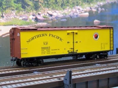
Here is an example of a sharper, tripod-mounted shot with a bounce card used to reflect some light on to the undercarriage of the loco (compare to the undercarriage of the rolling stock in the photos above).

This loco is now awaiting its turn in the paint shop to emerge repainted and re detailed as a proper B&O locomotive.
So by sheer serendipity I have managed to create a great photo location on the railroad. Now if I can just manage to put the trusses on the bridge and finish the riverbed, it should really look good.
Monday, November 9, 2009
Up Cranberry Grade
In July of 2008 my brother in law was visiting with his family and looking at the progress of my layout thus far when he made some comment to the effect that "I wonder why all the layouts that I see have no turns in them?" Now I don't know what layouts he was talking about since most layouts have too many turns. But I took it as a thinly veiled reference to my layout; yet I still managed to hold my tongue.
However, the incident spurred me to start the first section of the three tracks up Cranberry grade with a projected completion date of before Christmas. Cranberry grade is along the right wall as seen in the track plan. This section would involve building four new benchwork sections and laying out two 90 degree curves and two S-curves.
The radii of the curves on Cranberry are 64", 68.5" and 73". They were originally intended to be 64", 68" and 72" , but when I adopted Atlas switches in the M&K Junction area, I had to adopt their 4.5" center-to-center track spacing. These curves will handle big B&O steam like the EM-1 2-8-8-4 and the S1 2-10-2.
The curves were laid out using a homemade beam compass. At one end of the beam that I made for the beam compass are holes to hold a pencil to draw: the center line of the track; the limit of the roadbed on both sides of the center line; and the limit of the sub roadbed cutout on both sides of the center line. On the other end of the compass beam, and measured from the pencil hole representing the center line of the track, I have holes at 64", 68.5" and 73" that accept the pivot nail on the center column of the beam compass. Using this beam I could draw the five lines representing he 64" radius curve, move the pivot nail to the 68.5" hole and draw those five lines and finally lay out the 73" radius curves in a similar manner. By using a red pencil for the center line, green for the edge of the roadbed and blue for the 'cut-to' line at the edge of the sub roadbed the lines drawn on the plywood sub roadbed do not get too confusing. The picture that follows shows the guidelines laid out for two parallel curved tracks.

The beam compass was aligned square to the tangent (straight) track at the point where the curve was to begin (the Point of Tangency (PT)) then the pivot point of the compass was offset about 3/4 to 1 inch towards the inside of the curve to provide for an offset for an easement. Once positioned to my satisfaction, the pivot point of the beam compass was not moved until all curves in that location were laid out. This kept all curves concentric. I lay out my curves while the plywood sub roadbed is still flat.
All of my curves are eased. I initially tried to lay out easements using a cardboard template actually calculated using the cubic spiral formula. However, even in O scale the offsets calculated using the cubic spiral formula were so small that I worried that the effect on trains would be minimal. So I reverted to using a batten (a thin, narrow strip of wood) to lay out the easements.
Once all of the curves and easements are laid out, I take the plywood sub roadbed outside and cut to the blue lines, which represent the edge of the sub roadbed. Doing the cutting outside eliminates sawdust in the basement. Once the plywood is back on the benchwork, I begin adjusting the risers to the grade, if any.
Here is the track at the start of Cranberry grade.

These tracks are on a 1/2 percent grade which will increase to 2 percent to the left of this scene.
After this first 90 degree curve in the corner of the basement, I had to begin the back-to-back 'S' curves along the short wall of the basement (right hand side in the trackplan). Why such a complicated track arrangement? Because photographs, track diagrams and personal on-the-ground inspection show that there is little straight track on Cranberry Grade, and S-curves are common. A secondary, but very important, reason is to have a scenic attraction at this spot on the layout.
Now S-curves are supposed to be one of the toughest things to do on a model railroad; therefore I proceeded very deliberately. I used the guidelines in John Armstrong's "Track Planning for Realistic Operation" and laid out generous easements into and out of the 'S'. Armstrong reccommends that every S-curve have a section of straight at its center at least as long as the maximum truck center spacing of your longest rolling stock; in my case 85' passenger cars.
But generous easements and long straightaways left little of the sinuous 'S' curvature that would be a scenic attraction. So I minimized the central straightaway as much as I believed that I could get away with. To make sure it would work with the minimal straight sectgion I laid the flextrack on the plywood first and tested each S-curve on all three tracks with a passenger car coupled to a 30' hopper to accentuate the offsets of the couplers (per John Armstrong) to avoid a mistake that would be difficult to correct later.
Well, to make a long story short, by attending to detail it seems to have worked OK. My test trains seem to traverse this section of track quite well. Although I cannot run a through train yet, I run trains forward and reverse along these S curves with no derailments. Here’s a video of such a run (the train appears about 25 seconds into the video)
The train is moving up a 2% grade and rises about 10 inches moving along this section of track.
However, the incident spurred me to start the first section of the three tracks up Cranberry grade with a projected completion date of before Christmas. Cranberry grade is along the right wall as seen in the track plan. This section would involve building four new benchwork sections and laying out two 90 degree curves and two S-curves.
The radii of the curves on Cranberry are 64", 68.5" and 73". They were originally intended to be 64", 68" and 72" , but when I adopted Atlas switches in the M&K Junction area, I had to adopt their 4.5" center-to-center track spacing. These curves will handle big B&O steam like the EM-1 2-8-8-4 and the S1 2-10-2.
The curves were laid out using a homemade beam compass. At one end of the beam that I made for the beam compass are holes to hold a pencil to draw: the center line of the track; the limit of the roadbed on both sides of the center line; and the limit of the sub roadbed cutout on both sides of the center line. On the other end of the compass beam, and measured from the pencil hole representing the center line of the track, I have holes at 64", 68.5" and 73" that accept the pivot nail on the center column of the beam compass. Using this beam I could draw the five lines representing he 64" radius curve, move the pivot nail to the 68.5" hole and draw those five lines and finally lay out the 73" radius curves in a similar manner. By using a red pencil for the center line, green for the edge of the roadbed and blue for the 'cut-to' line at the edge of the sub roadbed the lines drawn on the plywood sub roadbed do not get too confusing. The picture that follows shows the guidelines laid out for two parallel curved tracks.
The beam compass was aligned square to the tangent (straight) track at the point where the curve was to begin (the Point of Tangency (PT)) then the pivot point of the compass was offset about 3/4 to 1 inch towards the inside of the curve to provide for an offset for an easement. Once positioned to my satisfaction, the pivot point of the beam compass was not moved until all curves in that location were laid out. This kept all curves concentric. I lay out my curves while the plywood sub roadbed is still flat.
All of my curves are eased. I initially tried to lay out easements using a cardboard template actually calculated using the cubic spiral formula. However, even in O scale the offsets calculated using the cubic spiral formula were so small that I worried that the effect on trains would be minimal. So I reverted to using a batten (a thin, narrow strip of wood) to lay out the easements.
Once all of the curves and easements are laid out, I take the plywood sub roadbed outside and cut to the blue lines, which represent the edge of the sub roadbed. Doing the cutting outside eliminates sawdust in the basement. Once the plywood is back on the benchwork, I begin adjusting the risers to the grade, if any.
Here is the track at the start of Cranberry grade.
These tracks are on a 1/2 percent grade which will increase to 2 percent to the left of this scene.
After this first 90 degree curve in the corner of the basement, I had to begin the back-to-back 'S' curves along the short wall of the basement (right hand side in the trackplan). Why such a complicated track arrangement? Because photographs, track diagrams and personal on-the-ground inspection show that there is little straight track on Cranberry Grade, and S-curves are common. A secondary, but very important, reason is to have a scenic attraction at this spot on the layout.
Now S-curves are supposed to be one of the toughest things to do on a model railroad; therefore I proceeded very deliberately. I used the guidelines in John Armstrong's "Track Planning for Realistic Operation" and laid out generous easements into and out of the 'S'. Armstrong reccommends that every S-curve have a section of straight at its center at least as long as the maximum truck center spacing of your longest rolling stock; in my case 85' passenger cars.
But generous easements and long straightaways left little of the sinuous 'S' curvature that would be a scenic attraction. So I minimized the central straightaway as much as I believed that I could get away with. To make sure it would work with the minimal straight sectgion I laid the flextrack on the plywood first and tested each S-curve on all three tracks with a passenger car coupled to a 30' hopper to accentuate the offsets of the couplers (per John Armstrong) to avoid a mistake that would be difficult to correct later.
Well, to make a long story short, by attending to detail it seems to have worked OK. My test trains seem to traverse this section of track quite well. Although I cannot run a through train yet, I run trains forward and reverse along these S curves with no derailments. Here’s a video of such a run (the train appears about 25 seconds into the video)
The train is moving up a 2% grade and rises about 10 inches moving along this section of track.
Subscribe to:
Posts (Atom)


