
Previous installments include:
Fun with LEDs
Fun with LEDs II
Fun with LEDs III
This chapter builds on the ideas and demonstrations in the previous ones, so if you are not savvy with LEDs, you may want to read these first. If you are knowledgeable about LEDs, you may find those and this installment to be old news.
Using Specialty LEDs
(c) 2011-2012 T. Terrance
There are a number of specialty LEDs and LED strips that are available that can be useful for model railroads. There are LEDs that flash, flicker, display red/green/yellow in a single LED; as well as tiny 'surface mount' LEDs and LED lighting strips, both in many colors. This chapter will show you how to work with some of these LEDs and along the way you'll have enough knowledge to build the electronic guts of a Flashing Rear End Device (FRED), maybe a model campfire or two as well as light passenger cars.
Flashing LEDs
Flashing (blinking) LEDs are available from many sources: Miniatronics 12-130-03 and other numbers; All Electronics CAT# LED-4; Radio Shack 276-312; Mouser and Digikey have too many part numbers to list here. Use their on-line product selectors search for keywords 'flashing' or 'blinking'. Flashing LEDs are usually found in red, green, blue, yellow and white. When selecting a flashing LED look for the operating voltage (usually 3-3.8 VDC), the current requirements (in milliamps) and the brightness in millicandellas (mcd); although there is a workaround for a dim flashing LED as we will see.
Flashing LEDs have a built-in 'chip' that makes the LED flash. The next photo shows the chip inside of a translucent yellow flashing LED.

Using most flashing LEDs is simplicity itself. Simply hook the LED up to 3V DC, observing the proper polarity, and they begin flashing - no resistor is necessary if you run them on 3V. Here's a photo of three flashing LEDs in a simple test setup.

In the front is a flashing red LED from Lumex (Mouser part #696-SSL-LX5093BSRD, Lumex part #SSL-LX5093BSRD), next is a yellow flashing LED also from Lumex (Mouser part #696-SSL-LX5093BYD, Lumex part #SSL-LX5093BYD); both of these LEDs were salvaged from another of my projects and have had their leads cut short. The LED in the back is the aforementioned All Electronics flashing red LED. The LEDs are plugged into a 'solder less breadboard' which is a gizmo electronics geeks use to quickly make up test circuits without soldering. 3VDC is being brought in on the red and black wires to the rear. The photo caught the All-Electronics LED flashing while the others were off.
Here's a video of those LEDs in action, first with the room lights on and then, from a different angle, with lights off.
One thing that you will notice is how feeble the yellow LED is compared to the red. This is normal, red is usually brighter than the other colors; pay attention to this if you are ordering colors other than red from Mouser or Digikey where you may have many flashing LEDs to choose from.
Most flashing LEDs flash at a rate of 1 1/2 to 3 times a second. This may be too fast for some model railroad applications. Can they be slowed down? Yes they can. By dropping the voltage these LEDs will flash at a lower rate. The flash rate will go down as the voltage goes down below the nominal 3 VDC. The rate at which the flash declines is not linear, that is in the first volt below 3 VDC, the flash rate slows down quickly. The flashing will stop altogether at about 1.5 VDC. Here are the flashing red LEDs from the first video clip (All Electronic (to the rear) and Lumex) flashing at 3 V, then 2 V (11 sec. into the video) and finally at 1.7 V (19 sec. to the end).
You'll notice that as the voltage drops, so does the brightness of the LED. Without going into theory, this is to be expected. But can this be fixed? Yes, in two ways. You can start with a brighter LED; then as the voltage drops the brightness will drop too, but it may still be bright enough to be usable. The problem with this is that the selection of blinking LEDs is rather limited and you may not find one bright enough for your needs.
The other way is to put another, brighter LED in series with the flashing LED. Another LED in series with the blinking LED will flash in sync with the flasher LED. (See
Fun with LEDs for an explanation and demonstration of LED series circuits). The selection of super bright LEDs is large and growing, so this method allows you to flash a super bright LED.
In the next video clip the dim flashing yellow LED from Lumex is wired in series with a high-brightness yellow LED with a clear lens. You see the LEDs flashing in sync with the room lights up and then in the dark.
If you remember from the previous installment, LEDs in series require a higher voltage than a single LED. The flasher LED requires about 3 VDC, a regular yellow LED requires about 2 V therefore we would expect that the combination would require 5 VDC to make it work; and indeed the demonstration that you saw above was running on 5 volts. Neither LED would light nor flash below 3.8 VDC. If you need to flash more than one additional LED, then the voltage required to run the circuit will increase about 2 V for each additional LED.
If you reduce the voltage to the series-wired LED+flasher the combination will flash more slowly; as the following video demonstrates.
In this video the red Lumex flashing LED is wired in series with a super bright red-orange, clear lens LED. The combination is running on 3.6 VDC. Compare the flashing rate with the video immediately above to see the effect of reduced voltage.
By the way, in the example above I've paired yellow flashers with yellow LEDs and red flashing LEDs with other red LEDs. However, the color of the flasher and the color of the LED that you put in series with it is totally independent, you can pair any combination of colors. This allows you to flash LED colors that do not come as flashing LEDs. The LEDs need not be of the same size either; the flashers that I have used are all 5 mm size (other sizes are available) but the series LED can be any other size, including surface mount LEDs. This allows you to flash surface mount LEDs which are not manufactured as flashers.
Are there other ways to flash an LED? Yes there are, but for simplicity the self flashing LED is hard to beat. When I write the chapters on building electronic kits and 'rolling your own' circuits, LED flashing circuits will figure prominently. At that time I'll talk about alternate flashers as are needed for grade crossings.
At this point you have enough information to make stationary flashers for most any scenery purpose, e.g. towers, advertising signs, bumpers, police and fire apparatus, etc. However, your power source needs to be low voltage DC. The easiest way to get pure DC is, of course, to use a battery. A pair of 'D' size batteries (3V) will power one of these flashers continuously for a year (I've actually done this experiment). If all of your LEDs are self-flashing, then wire them in parallel to 3V. If you have series strings of flashers and regular LED's, add more batteries to increase the voltage, as mentioned above. Hide the battery holder beneath the scenery and add an on/off switch and it will be a long time between battery replacement.
If you want to run your flashing LEDs from an rectified AC source, that includes any DC output of a power pack, 'wall wart' DC transformers, or a transformer/rectifier combination, you must follow some additional steps. First, you'll need to determine the polarity of the output terminals with a multi-meter as they are rarely marked. Next, the voltage is likely to be around 12V, especially using the fixed DC output from a power pack. Since the output of most power packs (as well as DCC and 'wall warts') is higher than 3-5 VDC you'll need a resistor in series with the LED(s) to drop the voltage a bit. Start with 1500 ohms and adjust up or down based on the brightness and flashing rate that you get. Most flashing LEDs will work fine with just a resistor to limit the current/voltage. Try this arrangement first and if it works, yuu can skip down to beyond the next couple of pictures. However, if your LED does not flash it may be that it does not like unfiltered DC. If your LED doesn't flash or is on constantly, you'll need to add a filter capacitor to the power supply output.
There are many different type of capacitors, (BTW, "cap" is used as shorthand for capacitor) the ones typically used for filtering are called 'electrolytic' capacitors. The key feature of electrolytic capacitors, for our purposes, are that they are polarized, that is they have a positive and a negative terminal; and must be hooked up with the proper polarity.
Capacitors are characterized by two values: their capacity (i.e. how much charge they can hold) and their voltage. Capacity is measured in microfarads (abbreviated uF). To filter a power supply for a reasonable current draw between 1/2 and 1 amp you'll need at capacitor between approximately 5,000 and 10,000 uF. As for voltage, a 35V or 50V cap should suffice. If you have a capacitor with higher capacity or higher voltage, it's OK to use.
Radial capacitors (that is, capacitors with both leads coming out of the same end of the device) can be obtained from: All Electronics (4700 uF, 65V, $1.65); MCM Electronics #31-5120(6800 uF, 35V, $5.14); Mouser #647-UVZ1V682MRD (6800 uF, 35V, $2.66); Mouser #647-UVZ1V103MRD (10,000 uF, 35V, $3.27); among many, many other sources. These types of capacitors are commodity items; so select one based on availability and price.

2200 uF, 35V Radial Electrolytic Capacitor
Filtering the power supply is straightforward. Attach the positive terminal of the cap to the positive output and the negative terminal to the negative output. That's it. Here's a video of a 1980's vintage MRC Tech II 2500 power pack with a filter capacitor on the fixed DC outputs running a flashing LED.
For this demonstration I've simply inserted the capacitor's leads under the fixed DC output terminals, observing the proper polarity. The resistor next to the flashing LED is necessary to reduce the approximately 12V output of the MRC 2500 to a value safe for the LED. This resistor is 1500 ohms, the value will be more to slow down the flashing rate. The value of the resistor will be less if you want to run a series-connected string of LEDs+flashers.
Now that we've discussed stationary flashing LEDs, what do you have to do to put a flashing LED into a car or locomotive? The simplest thing to do would be to battery power your mobile flashing LED. If you have space for a couple of 'AAA' batteries for 3 VDC (or four AAA batteries producing 6VDC for a series circuit) and an on-off switch you will not have to worry about reversing polarity on the rails, DCC square waves on the rails, over voltage or anything else. A battery-powered flasher will also flash when track power is off. AAA batteries will last a long time in this application.
If you must power the flashers from the rails then a rectifier and resistor will be necessary, as was demonstrated in the first installments (see Fun with LEDs II ). One additional component will be required to make the circuit function correctly; that component is a Zener Diode.
In a mobile application, the flashing LED may see as much as 18V from the rails and the chip inside of the LED needs to be protected form that high of a voltage. In addition, the use of a zener diode will allow you to have some control over the flashing rate by adjusting the voltage that the blinking LED sees.
A Zener diode is a special kind of diode which allows current to flow in the forward direction like a regular diode, but will also permit it to flow in the reverse direction when the voltage is above a certain voltage known as the breakdown voltage. When connected "backwards" (that is with its cathode connected to the positive voltage and its anode connected to the negative voltage) the zener will not conduct until it's breakdown voltage is reached. At or above the breakdown voltage the zener conducts and this trait can be used to limit the voltage that the flashing LED will see.
To accomplish this we put a zener diode across the + and the - after the resistor, but before the LED(s). The diagram below illustrates the set-up (click on the picture for a larger view).
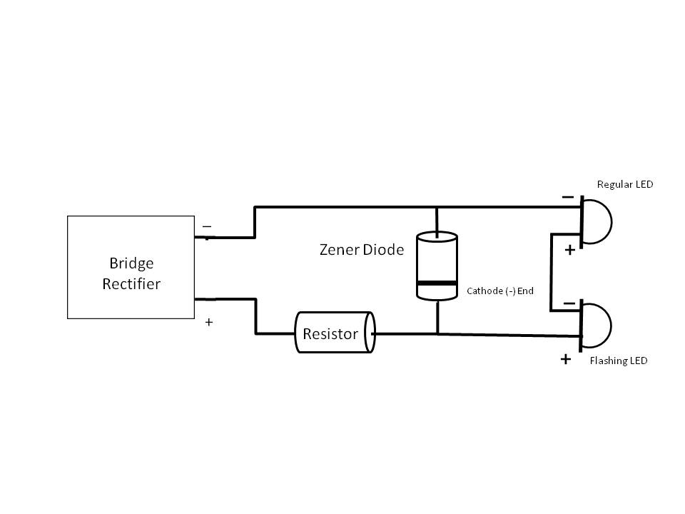
I've drawn this with two LEDs, if you want just one, just ignore the second. The cathode (negative end) of the zener is marked with a black band. It needs to be hooked up to the POSITIVE side of the circuit. The circuit works in this way: As the voltage from the track starts to rise, the LED(s) will begin to flash. When the voltage exceeds the zener's voltage, it will begin to conduct allowing current to flow from + to -. Once it starts to conduct, the voltage in the circuit will not rise beyond the zener's voltage. And, by the way, the flashing will be at a constant rate after the zener conducts and limits the circuit voltage.
It is imperative that the zener's connection point occur after the resistor. The resistor in this circuit limits the current through both the LED(s) and the zener. If the zener is placed before the resistor, when the zener conducts too much current will flow and the zener will burn out.
Zener diodes are characterized by their breakdown voltage and their ability to handle current. For any reasonable string of LEDs used on a car or locomotive, a 1/2 watt (500 milliwatt) zener should be sufficient. 1, 2 and 3 watt sizes are also available, although they can get physically large. Use the table below to select the proper zener voltage.
Flasher alone
|
Flasher + 1 LED
|
Flasher + 2 LEDs
| |
Normal flash rate
|
3V
|
5V
|
7V
|
Slow flash rate
|
1.8
|
3.8
|
5V
|
These zener values are suggestions, your LED or combination of LEDs may require a higher or lower voltage zener. Zener diodes usually do not come in even integer voltages, they will be something like 3.1V or 5.2V. Choose the value that you can find nearest to the ones in the table, getting the exact value is not necessary. Radio Shack has only 2 zeners (5V & 12V). NTE Electronics also has individually packaged zener diodes which can be found in stores dealing with electronic components. Mouser and DigiKey have a wide selection of zeners.
Here, I've built a mobile version of the flasher with a zener diode. This photo shows the rectifier, resistor and zener:

The cathode end of a 5.1 V zener is connected to the positive side of the circuit beyond a 1500 ohm resistor. the white wire is carrying the positive current to the remotely mounted LEDs and the blue wire is carrying the negative current.
Two series-connected LEDs are at the ends of those wires. One is the yellow flashing LED (Lumex) and the other is a 1.6 mm red, clear lens LED like the one in the next photo:

This tiny LED is small enough to be a F.R.E.D. in just about any scale including 'N'. Here's a video of both LEDs running on DCC track power (square-wave AC).
The yellow LED barely flashes while the tiny red LED shines brightly. This is just as well as the yellow flasher should be hidden with the rest of the circuitry.
If your flashing LED does not like the unfiltered DC that the rectifier outputs, then a small electrolytic capacitor will have to be added to the set-up.
As the final demonstration in this installment, here is a variation on the flashing LED, the flickering LED. These LEDs are found in LED "Tea Lights"; I bought mine at a dollar store 3/$1.

However, if you cannot find these tea lights near you, Electronic Goldmine has the bare LEDs: Flickering LED.
Here's a video of a flickering LED extracted from a dollar store tea light. First just the LED with its silicone-rubber candle top, then the flickering LED in series with a regular yellow LED.
Extracting the LED from the tea light is straightforward. Everything that applies to flashing LEDs applies equally to the flickering LED; voltage levels, series circuits, etc. A few of these hooked up to yellow, orange and red LEDs should make a convincing campfire. Especially if the LEDs were tiny surface mounted LEDs; but surface-mount LEDs are a story for another installment.
The next installment will deal with bi-color LEDs.


