
Text and Photos © 2011-2012 by Terry Terrance
If you haven't already done so, please read the original post on How to Convert Used PC Power Supplies for Your Model Railroad.
Since making that post I have been unhappy about the fact that these power supplies cannot be connected in series to produce sufficient voltage to run a DCC system. There are circuits that can convert DC at one voltage to DC at another voltage, either up-convert (boost) or down-convert (buck). These are called DC-to-DC Converters. DC-DC down-converters are fairly common but, even when you find them on the electronic surplus market, they are not inexpensive; and they usually do not have capacities in the multi-amp range. DC-DC up-converters are harder still to find and suffer from the same high cost and low capacity just like the down-converters.
There are many integrated circuits (IC) on the market that can be used to easily design an up-converter. However, doing so and building the circuit is beyond the abilities of some model railroaders.
A few weeks ago, I came across this circuit board being offered on e-bay from a vendor in China. Before the red flags go up (pun intended), I've ordered from Chinese vendors before and all of the transactions have gone smoothly by using Pay Pal.

This board is exactly what I was looking for. It will boost DC input voltages from 10-32 volts and produce an output voltage between 12-35V DC. The maximum output current is 6 amps. This is item number 090421 from a vendor whose handle is "jennyear". Cost is $13 with free (albeit slow) shipping.
The four screw-terminals on the end is for the inputs and outputs. Connecting the wires is straightforward.
I proceeded to test the circuit. I connected 12VDC to the inputs and a voltmeter to the outputs. I adjusted the potentiometer (the blue component with the screw on top) on the board to get an output of 19V, as you can see in the next photo.
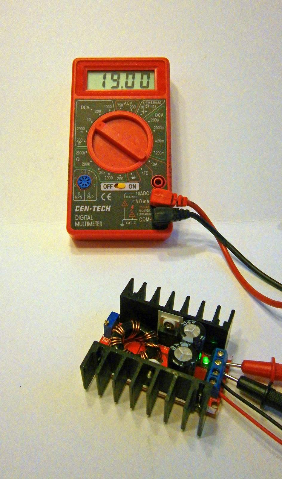
Notice that right behind the terminal strip there is an LED which is illuminated when the board is powered up. 19V is sufficient to run most DCC systems; besides if you keep the input voltage to your DCC system as low as practical, you'll get the maximum DCC current output, plus you'll minimize the generation of heat in this circuit. So far, so good.
Next I connected a power resistor (measured 20.2 ohms) to the output and put the meter in current mode to test for the output current. With an expected output of an amp at 19V, you cannot use an ordinary resistor for this, it will go up in smoke.

The power resistor is the device at the center. The 0.94 amps shown on the meter is the proper output for the voltage and the value of the resistor. After a few seconds of this output, the resistor became uncomfortable to handle, however the circuit board was still cool; very promising.
The next photo shows the trade-off for getting a higher voltage output from a lower voltage input. The power supply providing the 12V input is supplying 1.62 amps to get the 0.94 amp at 19V out.

This will not generally be a problem as your PC power supply can likely provide more than enough amps at 12V to get a 5 amp output at the 16-22V required to run a DCC system.
Next I took two 10 ohm power resistors and connected them in parallel to produce an approx 5 ohm resistance (I measured this at 5.5 ohms but this cheap multimeter is known unreliable at measuring small resistance values). This time I connected it to a PC power supply as the bench supply that I used in the first test would not supply enough current. As expected, the circuit output more current into this lower resistance; 3.6 amps as shown in the next photo.

At 19V/3.6 amps output the heatsinks on the circuit were warm and not excessively hot. I do not have any resistors of high wattage and low resistance to test this circuit further. However, I believe that an output of 19V/5 amps (95 watts) can be achieved.
Without further testing, here are some suggestions for finishing this circuit for use with a DCC system. First and foremost you must fuse the output. Even a momentary short circuit will fry the ICs that comprise this boost converter. I'd use a fast-acting 6 amp glass fuse (GMA-6A) and matching fuse holder. That may be hard to come by locally (although Home Depot does list these fuses on their website), so the fall back would be to use a 5 amp automotive blade fuse and fuse holder which you can find at your local auto parts store.
Use heavy wiring when wiring this circuit to your PC power supply and to your DCC system. You'll be carrying heavy current out of this circuit and even heavier currents will be feeding into it (probably in excess of 12 amps). 14 gauge would be a minimum. Be sure to heed my admonition in the article on converting PC power supplies to aggregate several distinct black (ground) and yellow (12V) wires from the power supply for the inputs to this circuit.
House this circuit in a metal project box; and a ventilated one would be much better as the circuit will produce heat during operation.
Adjust the circuit for a voltage a 2-3 volts above the minimal voltage needed to run your DCC system. The output of this circuit may sag under load (however, it was a stable at 19V with the 3.6 amp load) and you want it to stay above the minimum for your DCC system. Do not exceed the maximum input voltage for your DCC system.
Once connected to your DCC system, test that the circuit can supply sufficient output to allow the fast-acting DCC circuit breaker in your system to operate. Put a dead short on the tracks and test that the DCC output goes to zero instantly. If not, the circuit cannot handle the current surge and should not be used.
That's about it. At some point in the future I will use this set-up to power a Lenz Compact DCC system for my bench. At that point I'll write another blog post with the results. If you get around to doing something first, let me know the results.


