M&K Junction Railroad

M&K Junction Railroad
Another train of eastbound coal crosses the Cheat River

Saturday, May 31, 2014

Woah! It's Been a While.


2013 was not a good year for my model railroad.  The job that I had during the year put tremendous demands on my time, especially travel demands, and my railroad suffered for it.  The job suffered too and did not end well.  However for last couple of weeks I've started a new job and I'm very hopeful that this one work out better and I'll have more time for the railroad.

Essentially not much has been done on the railroad since my last posting execpt for last couple of weeks I've started to put up backdrops; more on that later.  Also during the year, and contributing to my lack of layout building, was the fact that in July I injured my knee and I wasn't able to get it repaired, again due to work requirements, until November. It's very, very difficult to build a railroad when you're on crutches.

That is not to say that I didn't do anything in model railroading during the year. I gave my clinic on the LaunchPad for Model Railroading at 3 NMRA conventions: one in April in Mississauga, Canada; another in July in Atlanta at the NMRA a national and the final one in October in Rockville, Maryland while I was on crutches.

In September, one of my daughters, who was going to an overseas teaching assignment, left her cat in our care. Because I did not know how the cat would react to the layout, I decided, reluctantly, to take most of the rolling stock off of the layout. The prospect of a cat getting on top of the layout and knocking rolling stock to the floor, at 60 bucks a pop for the average O scale car, was a prospect too horrible to contemplate. It was very emotional to take everything off of the layout thereby rendering it useless until such time as I could get the rolling stock back on.

Enough for the retrospective.   I've been stockpiling lumber in an attempt to get everything ready for completion of the main line.  I've taken the opportunity of most models being off of the layout to begin to put up the backdrops that I didn't put up when the bench work was built.  I've used 1/8 inch Masonite for the backdrop held up with 1x2 lumber, self tapping concrete screws and construction adhesive.  The corners are coved at about one and a half foot radius.  As of today about 1/2 of the layout is done.  Along one long wall of the basement; around the water heater (which involved several reverse curves in the Masonite) and along one of the short walls.  The new work was joined to the backdrop on the Cheat River grade, so now that part of the layout has a continuous backdrop.  See the photos which follow.


At M&K Jct. - The Cheat River photo backdrop will be replaced by a fresh print.


The first coved corner.  Here's where I learned that, contrary to what's on Masonite's website, Masonite will not bend down to 1 foot radius.


Approaching the water heater along the Cheat River grade.


Further along, the supports for the backdrop are ready.


The Masonite begins to curve with the Cheat River grade.


The water heater is behind the "S" curve in the Masonite in the center of this pix.


The new backdrop is joined to the already painted backdrop at the top of the Cheat River Grade.

Here are some shots of the joints taped. That's a job that I hate, but it's necessary.


Today, the first coat of paint went on and, I must say, that the painted backdrops change the entire look of the basement.  It's been a PITA, but I see that it's worth it.  Here are some shots looking down and then looking up the Cranberry grade.  


The second coat of paint will be finished by the end of the week.

During this work I've learned that the essential tool for putting up a backdrop of this kind is a air brad nailer.  With it properly adjusted I can nail the Masonite to the 1x2 supports (1x3 at the joints between sheets) and have the nail heads flush with the surface of the hardboard - no setting and filling of nail holes required.  The work went much faster with this tool.

Now that the backdrops are going up, I can begin scenery.  There was no point putting up scenery if a backdrop would have to be lifted into place over it.  I've gotten over my apprehension of doing scenery and I'm anxious to get started.


Wednesday, March 27, 2013

Report From India

Well, I can't say that my new job is not taking me to some interesting places.  I write this from Bangalore, India, where I am this week for a business trip.  Why is this relevant to Model Railroading?   India holds the #4 position for page views on this blog.  Now it may be that the readers from India are accessing one of the many pages on this blog about electronics. On the other hand is there a thriving model railroading community here?  Could they even be O Scale?

This trip to India was rather chaotic.  The date kept moving around and it was only finalized last Thursday (3/21); so I could not post it here and attempt to make contact with any Indian modelers.   However, if this trip is successful, I expect that I will be back at least once a calendar quarter, if not more often. So, if you are a modeler in India and would like to get together, let me know.

I also did not bring a camera this trip as I will be in the facilities of the Ministry of Defense and I certainly don't want to bring a camera in there.  However, as I get my bearings on travel to India, I intend to bring a camera on subsequent trips and, in the very least, get some railfan pictures.  I've seen videos of some incredible railroad-related situations here that I'd like to see for myself.

Saturday, February 23, 2013

Turnouts, Turnouts, Everywhere


Turnouts, turnouts, everywhere.  And curved turnouts at that.  I haven't posted in a while because I have been spending every available hour (which aren't many) either working on the layout, or building projects for the LaunchPad for Model Railroading blog.

In my haste to get ready for my last open house (I can't believe that it's coming up on a year now) I made a couple of stupid moves.  One of which I documented on this blog. I built a double crossover for the entrance to the helix, without measuring first whether it would fit (See The Scissors Crossover and Setback!).  To make up for this mistake, I put a single curved turnout into one track on the helix as a placeholder for a curved crossover to take the place of the abortive scissors crossover and I proceeded to build the helix on top of the location of the future curved crossover in order to have some progress to show for my April 2012 open house.  I knew this was not a smart move and that I'd have to pay for it later; well, now is later.

During 2012 I built a couple of more curved turnouts to finish the crossover as well as the entrance and exit from hidden staging (soon to be renamed lower staging).  Since January I've put those into place.

You'd think that my first run-in with a misfitted turnout would have taught me to "measure twice".  Unfortunately, no.  After finishing the curved crossover, which was fixed in place when I put the first switch down in April of 2012.  I found that the curved turnout that would lead off into hidden staging would not fit where I had intended for it to go.  It wasn't a question of rebuilding the turnout; no turnout (of any acceptable diverging radius) could avoid an unacceptably sharp reverse curve at that location.

So I had to move the turnout further up the helix to the location where I wanted to put another turnout leading from hidden staging. As a result the turnout for the track coming out of hidden staging is further up the helix and closer to the lead-in track so that an unacceptable grade and a fairly bad reverse curve results.  I now have a beautiful sweeping track leading into hidden staging and a short, steep, contorted track leading out of hidden staging where it connects to the helix.  Has anyone ever heard of someone who built staging that needed helpers to get trains out of it?

I kick myself because I should know better; and I knew at the time that I was potentially making mistakes.  Not the least of which I now have to build a fairly complex switch plant between the turns of the helix.  Which, among other things, required that I relocate some of the helix supports which were now standing where track had to pass.

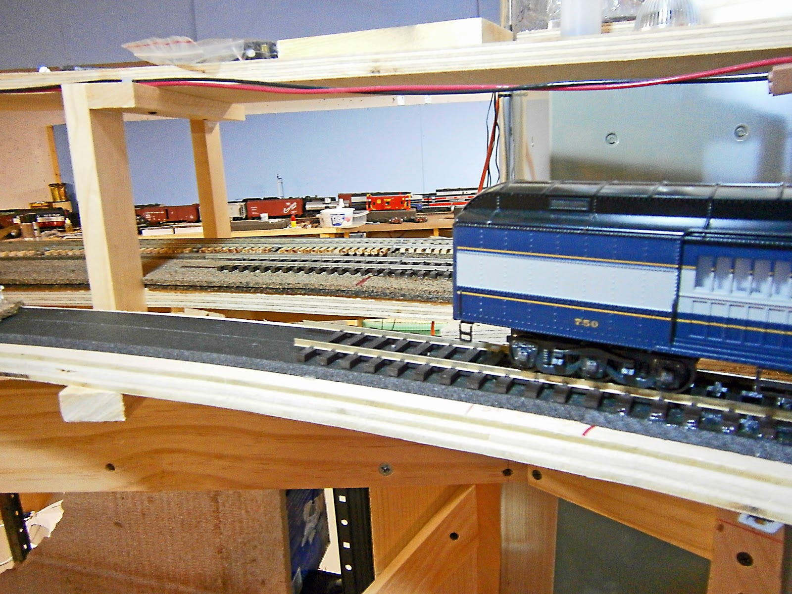
Enough of the kevtching already!  Let's look at some photos.  The connection of the track leading into hidden staging, shown in the last blog post has been completed.  Here are a series of shots of the passenger car, now able to run all the way to the inner track on the lower level of the helix.


This last shot is how my 1/48 scale track gang sees the car merging into the lower level of the helix.

The switch plant that I've built in between the level of the helix looks like this:


Here we're at the beginning of the curved crossover looking uphill on the helix from the inside.  Across the aisle is M&K junction and some standing trains.  The crossover goes between the outer and the inner track on the helix; it's facing point.


About mid-way through the curved crossover here.


The completion of the crossover plus the track into hidden staging is visible on the left.  Beyond the foreground, on the opposite wall of the basement, is Cranberry grade.


Here are a couple of views looking downhill somewhat earlier during construction and the track to staging is clamped and weighted waiting for the glue to dry. 

Finally a couple of track-gang level views.


All of these turnouts are hand-built and, no, they don't have four spikes per tie.  Most of the non-PC board ties are glued on because these will be hidden under scenery to the viewer in the aisle.  Guard and wing rails are extra long to capture the wheels long before and after they pass the frog.

Over on the other side of the helix, the approach track from hidden staging was mocked up in foam core (as was this track) because I could not use my beam compass to lay out the curves (too many obstructions).  Here are some pictures of how that looks.


In the very busy shot above, the lower turn of the helix is shown with one track in place.  The current end of track on the helix is right where you can see the base of a cordless drill.  The support structure for the second turn of the helix does not extend beyond this point.  In the middle ground you can see the foam-core mock-up of the track out of hidden staging.  It will join the lower turn of the helix off camera to the right and behind the photographer.  Follow it left and you can get a sense for how fast it has to drop.  The grade will face approaching trains.

The grade can be seen in this somewhat more sideways view.


Although it's somewhat exaggerated by the wide angle setting on the camera's lens, the drop really is steep. Although I have not adjusted the foam core to final grade, it calculates out to something near 4% between where it will join the helix and where it ducks under the helix.

Adding insult to injury, the current alignment has a reverse curve with no room for a straight section between the curves - a no-no according to John Armstrong.


As you can see in this shot.  Where the two pieces of foam core are disconnected, one curve butts against the other with about an inch between them.  I think that I can realign this section to get some tangent between them, but will it be enough?


Tuesday, January 29, 2013

There's Sawdust On The Floor Again


There's sawdust on the floor again and odd-shaped pieces of wood.  And that means that work on the layout has resumed!

2012 was not a good year for my layout.  I did essentially nothing on the layout after my open house in April 2012.  This was because I lost my job in March.  I could not justify,  in good conscience, spending money on the layout while I was on unemployment; especially given the poor job outlook.  

So, while I had the time I did not have the means.  I also discovered that searching for a job is, essentially, a full time job.  I spent 5-6 hours on most days doing my job search.

I did do some painting on the layout, built a few turnouts out of rail that I had on hand, assembled some kits.  But no matter which project I started, I always ran short of something before it was completed and, because of my "no purchases" rule, things progressed slowly, if at all.

However, I wasn't totally out of model railroading for most of the year.  I wrote articles, several of which were accepted; and the first has been published in January of this year.

I did 3D design; spending the money earned from the articles on test printing the models.  I justified this by rationalizing that the models would make me money in the long run - I've yet to break even.  And I did the Tsunami heat sinks - which will just reach break even when the next batch is sold.  

The moral of all of this is be kind to your garage manufacturer of model railroad items, he's probably doing this out of love rather than for profit.  I'm glad to be working again!

Last weekend was the Springfield model railroad show and I attended.  But the previous two weekends were spent working on the railroad.


This is a passenger car that I am using to test the clearances where the newly-added track into hidden staging runs behind and close to the backdrop for the Cheat River grade. The car is just about to pass under the lower level of the helix, immediately above.

The tracks into and out of hidden staging are on such good-looking curves that it's a shame to cover them up and I am debating whether to let these approach tracks show by creating a small section of double deck layout.

This next photo shows the car at the point of closest approach to the backdrop.  The car has just passed under the helix, which is now above and to the right.  The clearance here is not as tight as it looks from this shot.


Finally, here's the current end-of-track.  The passenger car is still on the track leading into hidden staging.  Behind and beyond the car to the left, you can see the current end-of-track for the inner track of the two-track helix.  Both of these tracks will converge at a curved turnout, which is off-camera to the left, and merge into a single track which continues up the helix.


Hopefully this coming weekend I can finish this bit of work and start on the exit track from hidden staging.  It has some close vertical clearances, a tight reverse curve and a steep grade.  That's the result of adding staging as an afterthought without prior planning.


Saturday, December 15, 2012

More on the Launch Pad for Model Railroading


In this installment I will share the MSP430 code for a traffic light sequencer, but before I do, I believe a few words need to be said about powering the Launch Pad.

TI has designed the Launch Pad to be powered in two ways.  The most straightforward is via the USB connection.  This is how most experimenters will use it.  Your computer puts out regulated 5V on the USB cable.  The Launch Pad converts this 5V to 3V to power the microcontrollers on board (there are more than the one that you are programming).  

If you want to power the Launch Pad on your layout this way I would suggest that you get a USB powered hub with a lot of output ports.  Then get some USB "Male A" to "Female A"  extension cables (sometimes the dollar store has these, if not try All Electronics).  Use  the extensions to connect the hub to your Launch Pad's USB cable.  Now your Launch Pads are powered with no muss, fuss or bother and the cost is not great. Non-powered hubs can be cascaded from your powered hub to feed more Launch Pads. Not a bad option if your layout is not too large.

If your layout is really large or the distances between Launch Pads is long, you may want to run a power bus for the Launch Pads.  This bus must be clean, pure, regulated DC - the output from a spare power pack will not do.  The voltage on this bus must be between 3V and 3.3V and cannot exceed 3.6V.

The Launch Pad documentation tells you which jumpers to disconnect to use external power.  A good power source would be a converted PC power supply.  You may be able to find a wall-wart that puts out 3VDC, but it has to be regulated.  Another inexpensive option, that I have not tried, may be the Philmore MW122A power supply (about $25 but available from MCM Electronics for $19 and when on sale for as little as $15).  This looks like their old battery replacement unit but they claim full regulation and low ripple.  Whatever you use, maintaining regulation over very long runs can be a problem.  I have purchased some inexpensive regulator boards off of e-bay that could be used to take clean but unregulated DC and regulate it to 3V right at the Launch Pads.  I'll let you know how my experiments turn out.

Using external power unfortunately prevents you from using the USB port for a future network of Launch Pads or from potentially controlling your Launch Pads from a central location.  

Enough about power, on to the traffic light sequencer.   

Traffic Light Sequencer

This program uses timing loops just like the alternate flasher, but I have used some different coding structures and the timing loops are of uneven  durations.

First, how do traffic lights operate?  Traffic lights control two intersecting bidirectional streets.  Lets refer to one route as East/West (E/W) and the other as North/South (N/S).  A regular 3-color traffic light then has four states:

E/W - Red            N/S - Green
E/W - Red            N/S - Yellow
E/W - Green         N/S - Red
E/W - Yellow        N/S - Red

And then the cycle repeats.  The green and the yellow cycles will have different durations and the red cycle will be the sum of the green and yellow cycles - so the three signal aspects have three different durations.  My observation of the traffic lights outside of my office indicates that the yellow cycle lasts for about 1/8 as long as the green.

This is all of the information that we need to know to program our traffic light sequencer. The table above tells us which lights to turn on or off for each cycle.  We need to define two timing loop counters - which we will call 'green' and 'yellow'.  We do not need to define one for red since it is the sum of green and yellow.

Refer to the listing at the end of this post as I walk through the code.  This is not an attempt to teach you how to program in "C" (I'm hardly qualified for that); but simply to explain the workings of the program.

After the declaration of the main program (main.c) come several statements that tell the compiler - the program that executes on your PC and builds the program for the microcontroller - some things that it should do.  One of these is which, of several hundred TI microcontrollers, we want to build a program for (i.e. target).

Then a number of variables are declared.  Variables are numbers whose values, as their name implies, can be changed.  In this program, almost all of them are used as constants; only t's value changes.  The comments after each variable declaration explains its use.  A value of 900,000 in 'green' causes a delay of about 16 seconds for the green lights and the value 112,500 in 'yellow' a delay of about 2+ sec. for the yellow lights.

Under the banner "BEGIN MAIN PROGRAM"  the part of the code that actually executes on the microcontroller begins.  The first job is to turn off the watchdog timer (it's important to do, but I won't explain why now).

Next we set up the pins on the microcontroller.  This involves two operations for each pin.  First, the pin has to be defined as an output; followed by setting the output "on" (that is, telling the microcontroller to put 3V on the pin).  The comments tell you which pin is being set and what it is used for.  Inside of the parentheses is the internal port and bit number that is being used (more on this in another post).

Next under the banner "DELAY WITH ALL SIGNALS ILLUMINATED FOR LAMP CHECK" I do something that is not necessary, but is nice to have.  All of the signals have been turned on by previous code, so I introduce a delay loop of a couple of seconds with all of the lights so that you can do a visual lamp check.  

A word about delay loops.  It is possible to get precise timing out of the microcontroller; but it's an involved process and not required for this prigram.  Approximate times can be established by using loops to count up or down to/from a number and the time it takes the microcontroller to do this counting produces the time delay.  This loop tells the microcontroller to count using the variable 't' as a counter from t=0 to the value of 'start_up_delay', which has been set to a value of 50,000.  After the loop is finished, 't' is set back to zero so that it can be used as a counter in the next delay loop.

Under the banner "BEGIN MAIN LOOP" we begin the part of the program that will execute indefinitely so long as power is applied.  The "while" statement begins an infinite loop; once execution reaches this point everything between this statement and the end of the of the "while" statement will run indefinately.

The first sequence of setting the traffic lights begins after the banner "Begin Sequence E/W - Red  N/S - Green"; like the first state in the table above.  Since the first time through this loop all of the lights will be on after the lamp check, we have to not only turn on the appropriate Red and Green signals, but turn the others off as well.

After the lights have been set, the program enters a delay loop that counts up to the value in the variable "green".  The microcontroller will take about 16 seconds to count up to 900,000; "t" is then reset to zero and we go on to the next sequence.

Here's where this program differs from the alternate flasher program.  In the alternate flasher, the instructions turning the LEDs on were inside of the loop.  So the LEDs were turned on several thousand times while the loop executed.  In this program we set LEDs once and then just idle in the loop while we count up.

The next sequence "E/W - Red   N/S - Yellow" begins with the comment that we  do not have to set the E/W signal to red because it's red already; but we're going to do it anyway.  This makes the code clearer and more self-contained, but could be eliminated if we were running out of code space or time - which we're not. At the end of this sequence, we count up to the value in the variable "yellow", which produces a delay of a little over 2 seconds.

The next two sequences operate in much the same way as the first two.  After the timing loop of the last sequence, the right hand curly brackets closes the "while" statement infinite loop and the program returns to the first sequence.

Here's a video of the circuit in action.  I've made a daughter board to connect six LEDs and resistors (270-300 ohm) to the Launch Pad's pins that I have defined as output. The daughter board obscures the Launch pad which is below the daughter board. The layout of the LEDs follows the layout of the microcontroller's pins and not the arrangement of a traffic light signal head, but you'll see the correct pattern of lights in red, yellow and green.


You can download the text file of the code here:

Traffic Light Code
 
If you want to try your hand at modifying this program here are a couple of suggestions.  If you want to have more than three indications on the signal, to add turning arrows for instance, you would add additional states to the state table.  You'd have to define more output pins for the turning arrow LEDs, then add a couple of states where both main signals are red and the E/W then the N/S arrows are illuminated in turn before returning to the green-yellow-red sequence.

If you want to add a third route through the intersection, you will need to add a column to the state table then re-sequence the lights to accommodate the three routes. New output pins will have to be defined for the additional signals for the third route.

For the neurotic, who want the maximum attention to prototype detail, I have two suggestions.  At most intersections one route through the intersection is usually more heavily traveled and is allowed more time on green than the other route.  This would be an easy modification.  Simply define two green and two yellow loop counters - a longer one for the superior route and a shorter one for the inferior route.  Substitute them into the code where appropriate for 'green' and 'yellow' and the timing loops will adjust accordingly. 

The other suggestion is for the (exceedingly neurotic) advanced  programmer.  Build in a 'soft start' and 'gradual fade' for the LEDs to make them look more like incandescent lights. This could be accomplished in two ways. Build a nested timing loop where the LED is on for a short while followed by an off period, followed by a longer on period, shorter off period..., etc. until full brightness is reached.  Full brightness is held for a the duration of the signal and then the process is reversed.  The soft start and gradual fade would be much less than a second each and the loops would probably be only hundreds of counts long at the beginning and end. What you are doing is creating a crude Pulse Width Modulation (PWM).

The other apporach would be to use the on-chip PWM generator to do this function for you. I'll be doing PWM for a future project, so we'll see how this comes out.

These options demonstrate the versatility of the microcontroller.  You can buy a traffic light circuit kit, but it's a fixed green-yellow-red sequence without any ability to add additional lights or routes or modify the timing.

 
This has been a long post with a lot of information. The code for the basic traffic light sequencer follows. Don't cut and paste this into Code Composer Studio as the embedded HTML that allows it to display properly will mess up the compiler. Use the link above to get a text file of the program. (BTW Blogger has really honked-up the indentation this time, and I cannot seem to get it fixed, sorry)


//
//
//
// Traffic Light Sequencer
// COPYRIGHT 2012 T. TERRANCE
//                                
// Provided  under a Creative Commons Attribution, Non-Commercial                       ////
// Share-Alike,3.0 Unported License                          
//
// TARGETED TO MSP430 LANUCHPAD W/MSP430G2553 PROCESSOR
//
//


/*
 * main.c
 */ 
 
#include <msp430g2553.h> //This instruction tells the compiler what microcontroller you are compiling this for.


volatile long t=0;        //Define loop counter t and set it to 0
volatile long green = 900000;   //Define loop counter green and set it to 900,000
volatile long yellow = 112500; //Define loop counter yellow and make it 1/8 of green
volatile long delay=15000;   //Define delay waiting period used to latch the signal indication and set it to 15000
volatile long start_up_delay = 50000;   //Define delay waiting period used to flash all of the signals at start-up and set it to 50000


////////////////////////////////////////////////////////////////////////////////////////////
//                      
//     BEGIN MAIN PROGRAM            
//                      
////////////////////////////////////////////////////////////////////////////////////////////


void main(void){


WDTCTL = WDTPW + WDTHOLD;  //Stop Watchdog Timer


P1DIR |= BIT0;  //sets E/W RED SIGNAL pin #2 (Port 1, Bit 0) to output and set to on
P1OUT |= BIT0;

P1DIR |= BIT4;  //sets E/W YELLOW SIGNAL pin #6 (Port 1, Bit 4) to output and set to on
P1OUT |= BIT4;

P1DIR |= BIT5;  //sets E/W GREEN SIGNAL pin #7 (Port 1, BIT 5) to output and set to on
P1OUT |= BIT5;

P2DIR |= BIT0;  //sets N/S RED SIGNAL pin #8 (Port 2, BIT 0) to output and set to on
P2OUT |= BIT0;

P2DIR |= BIT1; //sets N/S YELLOW SIGNAL pin #9 (Port 2, Bit 1) to output and set to on
P2OUT |= BIT1;

P2DIR |= BIT2; //sets N/S GREEN SIGNAL pin #10 (Port 2, BIT 2) to output and set to on
P2OUT |= BIT2;


/////////////////////////////////////////////////////////////////////////////////////////////
//                      
//  DELAY WITH ALL SIGNALS ILLUMINATED FOR "LAMP CHECK"     
//                      
/////////////////////////////////////////////////////////////////////////////////////////////


for (t; t < start_up_delay; t++)  //delay loop
  {

  }
  t=0;


  /////////////////////////////////////////////////////////////////////////////////////////////
  //                      
  //     BEGIN MAIN LOOP              
  //                      
  /////////////////////////////////////////////////////////////////////////////////////////////


  while (1) // while (1) is always true, so this is an infinite loop
  {

   ///////////////////////////////////////////////////////////////////////////////////
   //     Begin Sequence - E/W Red, N/S Green
   //
   ///////////////////////////////////////////////////////////////////////////////////


   P1OUT |= BIT0;  //turn on E/W RED SIGNAL
   P1OUT &= ~BIT4; //turn off the E/W YELLOW SIGNAL
               P1OUT &= ~BIT5; //turn off the E/W GREEN SIGNAL

               P2OUT &= ~BIT0; //turn off the N/S RED SIGNAL
               P2OUT &= ~BIT1; //turn off the N/S YELLOW SIGNAL
               P2OUT |= BIT2;  //turn on the N/S GREEN SIGNAL

               for (t; t < green; t++)  //delay loop for one green time period
        {

        }
             t=0;

       ///////////////////////////////////////////////////////////////////////////////////
       //     Begin Sequence - E/W Red, N/S Yellow
       //
       ///////////////////////////////////////////////////////////////////////////////////

             //the E/W signals should not have to be reset
             //but do it anyway

       P1OUT |= BIT0;  //turn on E/W RED SIGNAL
       P1OUT &= ~BIT4; //turn off the E/W YELLOW SIGNAL
           P1OUT &= ~BIT5; //turn off the E/W GREEN SIGNAL

                //the N/S red signal should not need to be reset
                //but do it anyway


           P2OUT &= ~BIT0; //turn off the N/S RED SIGNAL
    P2OUT |= BIT1;  //turn on the N/S YELLOW SIGNAL
    P2OUT &= ~BIT2; //turn off the N/S GREEN SIGNAL


         for (t; t < yellow; t++)   //delay loop for one yellow time period
          {

          }
          t=0;


         ///////////////////////////////////////////////////////////////////////////////////
         //     Begin Sequence - E/W Green, N/S Red
         //
         ///////////////////////////////////////////////////////////////////////////////////

         P1OUT &= ~BIT0;  //turn off E/W RED SIGNAL
    P1OUT &= ~BIT4;  //turn off the E/W YELLOW SIGNAL
    P1OUT |= BIT5;   //turn on the E/W GREEN SIGNAL

    P2OUT |= BIT0;   //turn on N/S RED SIGNAL
    P2OUT &= ~BIT1;  //turn off the N/S YELLOW SIGNAL
    P2OUT &= ~BIT2;  //turn off the N/S GREEN SIGNAL


          for (t; t < green; t++)   //delay loop for one green time period
           {

           }
           t=0;


         ///////////////////////////////////////////////////////////////////////////////////
         //     Begin Sequence - E/W Yellow, N/S Red
         //
         ///////////////////////////////////////////////////////////////////////////////////


                           //should not have to reset E/W red signal
                           //but do it anyway

      P1OUT &= ~BIT0; //turn off E/W RED SIGNAL
      P1OUT |= BIT4;  //turn on E/W YELLOW SIGNAL
      P1OUT &= ~BIT5; //turn off the E/W GREEN SIGNAL

                        //should not have to reset any N/S signal
                        //but do it anyway

     P2OUT |= BIT0;  //turn on N/S RED SIGNAL
     P2OUT &= ~BIT1; //turn off the N/S YELLOW SIGNAL
     P2OUT &= ~BIT2; //turn off the N/S GREEN SIGNAL


     for (t; t < yellow; t++)  //delay loop for one yellow time period
            {

            }
          t=0;


  } //close while statement, back to top of infinite loop


} // End Main