M&K Junction Railroad

M&K Junction Railroad
Another train of eastbound coal crosses the Cheat River

Friday, April 6, 2012

Setback!

I've been able to get a lot accomplished this week, although I have had a layout-related disappointment.

I rewired and rehung the lights on the Cheat River Grade and the new arrangement is much improved.

Unfortunately, the scissors crossover that I sweated over building (literally and figuratively) for the last several weeks did not fit where intended. I should have laid this out in CAD; I even should have thought through the geometry before building it. I can see now that it will require a curved crossover to fit the space. I believe that given enough time I could build a curved scissors crossover, but it would not be complete in time for my next open house; so I will build it as two single curved crossovers. To do so I have just ordered more code 148 rail. However, this setback practically assures that I will not have the helix finished by the date of the open house.

In the meantime, I have begun laying the track on the helix, over where the scissors crossover would have been and it looks like this:


The roadbed in the foreground is on the helix and you are looking towards the Cheat River Grade in the illuminated space towards the rear. The roadbed is dual layer cork on top of camper (topper) tape. The track ducks under the basement stairs in this location. We don't let physical obstacles deter us!

Saturday, March 31, 2012

The Scissors Crossover

Before track can be laid on the Mother of All Helices (MOAH) I had to build a scissors crossover. Since the helix is designed to be serial storage for trains, the crossover is at the entrance of the helix and will allow me to store trains from either direction on either track of the helix. It will also allow trains into and out of hidden staging which will have a connection on the inner track on the lower level of the helix.

To this end, I had built four Fast Tracks jig-built turnouts (2 right hand and 2 left hand). I intended to build these into the crossover. Unfortunately, I could find no good information on building a scissors crossover. Fast Tracks had printable templates for building one in HO or smaller scales, but they were not available in O scale; and they were for a much tighter track center spacing than I was using so they could not be enlarged to equivalent O scale.

The NMRA had no data on building one using the #6 turnouts that I had on hand. Particularly I wanted to know the degree of the crossing in the middle as a function of the turnout number and the track center spacing.

Paul Mallery's "Trackwork Handbook" had instructions for scratch building a simple crossing and it was of some help.

I guess that I could have calculated the angle of the crossing using geometry had I put my mind to it. Instead, for better or for worse, I decided to wing it and improvise as I went.

So I started to lay out the crossover on the back of my 2x4 ceiling tile where I build most of my scratch built track. The two left-hand turnouts were positioned first as these form the facing-point crossover which will be the most often used route through the crossover. The turnouts had been built with extra-long rails on the diverging routes and I joined these to form a continuous route through the crossover.

Here's what that looked like:

IMG_0769_edited

IMG_0770_edited

Next, it was time to start fitting the right hand turnouts. The straight legs of the turnouts were temporarily joined with rail while the diverging leg was butted against the left hand crossover. These pictures show it best.

IMG_0771_edited

IMG_0772_edited

To keep the straight routes in line and in gauge, I used Fast Tracks "Sweep Sticks". I had what I thought was a brilliant idea to cut one of the sweep sticks into a tool that would hold the intersecting rails in gauge as well as to the proper angle while they were being soldered to the previously laid crossover. The next photo shows how I used sweep sticks.

IMG_0773_edited

The angle-cut sweep stick did not work out as well as I had planned. I did not have enough hands to hold the rail tight against the sweep stick while wielding the soldering iron and the solder. However it worked well enough to keep the track just within tolerance by the NMRA gauge.

Once the first right hand turnout was soldered in place the problem of how to align the turnout on the opposite side arose. This time I had better luck with improvising a tool. I made a tool out of 3/4" x 1/8" aluminum, notched to fit over the in-place rails and which would hold the off-side turnout rail in alignment with the turnout already soldered in place.

IMG_0793_edited

IMG_0800_edited

The detail shot shows how the tool is held in place with wooden clothes pins with their handles turned around and end-for-end so that the straight legs are pinching the tool to the rail. It's important that a tool like this be used on the gauge side of the rail and not on the off-side.

The tool, with a lot more clothes pins, was also used to align the rails in the center of the diamond:

IMG_0809_edited

Here, the two running rails in the center of the diamond are aligned and soldered in place:

IMG_0816_edited

Here's the scissors crossover with all running rails in place:

IMG_0822_edited

Now came the really tedious part - the guard rails. The guard rails will have to have part of their base removed to fit against the running rails; and where their ends butt against the running rails they will have to be filed to an angle as well as having the base relieved to fit snug against the running rail.

Before the guard rails could be fitted the flange ways had to be filed through the running rails. I tried, without success, to use a Dremel tool for this purpose. Even though I have a cutter that it the exact size for an O Scale flange way, I could not hold and guide the tool accurately enough to cut a good flange way. In addition the tool had a tendency to catch on the rail and become uncontrollable.

During the fitting of the guard rails and the filing of the flangeways, I ran into a curious problem. After checking the work with the NMRA gauge, I would run a truck through. This particular truck was removed form a car where I had replaced all of the wheel sets with Precision Scale wheel sets. Oftentimes one wheel set on the truck would have no problem going through, but the other would hang, usually catching the back of the wheel set on the guardrail or in the flange way. For the longest time I did not question what are supposed to be high-quality wheel sets, and I did a lot of extra filing to get the thing to pass through.

Finally frustrated with the amount of filing that I was doing, I checked the wheel sets. Sure enough one wheel set on the truck was wide-gauge. So I got the other truck from the original car and start using it - and the problem persisted! This time I checked the wheel sets early and one wheel set on this truck was wide too! So out of four wheel sets, from a reputable company, two were out of gauge. Just goes to show, take nothing for granted.

Here are pictures of the completed scissors crossover.

IMG_0835_edited

IMG_0840_edited

IMG_0836_edited

IMG_0831_edited

IMG_0827_edited

Placement of the PC ties was ad hoc and did not follow any pattern. Fortunately, this scissors crossover will be hidden from view (but still easily accessible) inside the helix; so the fact that it's not competition quality is not an issue. Still it's a shame that no one will admire my handiwork.

I will have to build another one of these for the top end of the helix, to get re-routed trains back on their proper tracks. But that's a job for April.

Friday, March 2, 2012

It's Itsy-Bitsy

I've finally finished a project that I've been thinking about since 2007, namely, creating a scale B&O Color Position Light (CPL) dwarf signal. What's the big deal, you ask? It's to exact scale and it's itsy-bitsy.

The story starts at the 2007 O Scale National Convention. I attended a clinic by a gentleman who was using 3D Computer Aided Design (CAD) and a jeweler's 3D wax printer to create O Scale parts. He would design a part in the CAD program, send it to the wax printer which would print a copy of the design in wax. The wax model would then be used to make a rubber mold, the mold would make more wax copies which were then used in a conventional lost-wax process to produce the final parts in brass.

While this sounds complicated it was, for its time, an inexpensive and fairly simple way to get to finished parts if you needed more than one copy.

At the time I had been looking into various 3D printing processes concentrating on stereo lithography (SLA), but the costs of those machines were astronomical and having models produced on them was far too expensive, even for one piece; so the wax printer/lost wax process was promising.

Soon after the convention I settled on the B&O dwarf signal as the model that I wanted to produce in O scale. It had never been done to scale; MTH (and, I believe, Right-o-Way) having produced grossly over sized versions for the 3-rail O gauge market. Also, I had the plans for the General Railway Signal Type 'VA' B&O CPL dwarf signal so that would make it easier.

Here's a picture of the prototype.


This dwarf has two additional markers and a sign on top, but the basic signal is the lower eight lights.

The CPL dwarf is a difficult signal to model. Eight lamps, each with visor, on a small target would be difficult and expensive to produce by conventional machining; even to build a single master for reproduction by casting. Many 3D printing processes, like fused deposition modeling (FDM), are too coarse to produce a small, finely detailed model.

In 2009 I took a job where we use 3D printing (out shopped) to check designs before we commit them to production. I had a chance to sample several different 3D printing processes as well as get some exposure to 3D CAD. Now I had access to the tools and some people who could help me out.

Here's what the 3D model of the basic CPL dwarf signal looks like:


This model is somewhat simplified. The nuts and bolts on the case are not reproduced; nor are the ribs on the backside of the case back; nor are the edges of the case rounded. As it turns out, none of these are visible at normal viewing distances.

I still needed to find a supplier that could produce the models without charging $80-100 for each one. Enter Shapeways. I'm not the first modeler to discover Shapeways 3D printing service. Their service is unique; they offer several different 3D printing processes, they offer worldwide shipping, their prices are reasonable and they are modeler-friendly.

I designed the model to use the full capabilities of Shapeway's "Frosted Ultra Detail" (FUD) material which could hold the smallest features out of all of Shapeway's processes. FUD is a 3D printing process called 'PolyJet', which prints a part using a UV-cured plastic shot from a multi-nozzle print head much like your inkjet printer prints. The signal's shell, which is hollow to allow for illumination, is made to the minimum thickness allowed by the process. With some trepidation as to how they would appear, I made the visors a little thicker than the minimum for strength.

Since the model was done on a heavy-duty 3D CAD program (Solid Works) it passed all of Shapeway's tests for printability. After I uploaded the model to Shapeways, I discovered, to my delight, that the model could be produced for well under $10 (US); so I ordered one.

When it arrived, it struck me just how tiny this thing is. It's so small that I am convinced that it could not have been produced to scale, with scale-sized visors, by most other process, especially casting. Here's what the model looks like.


The model is on the dining room table's tablecloth and that's the weave of the fabric that you can see. This gives you some idea of the size of this dwarf. I'm really happy with the way the visors came out. They are 20 thousandths of an inch (less than one inch in O scale) and although that is thicker than the prototype, you cannot tell from looking at it.

Here's a picture on the layout:


That's an O scale E7 in the background. The O scale figure is 1.43" tall (36.43 mm).

I have made some changes to the back cover of the signal, which is a separate piece, and I have another batch on order. When those arrive I'll experiment with painting (Shapeways could not advise me on compatibility of FUD with paints) and illuminating. I'm sure that this signal can be illuminated with 'chip' LEDs; but that will require me to design and lay out a circuit board, which will take a while.

Thursday, February 23, 2012

Photo Backdrops Made Easy Part 2

It's finally done! Here's the second video on Photo Backdrops. This installment covers photo taking and printing. This video completes the basics of making photo backdrops. You can see the first video in the series here: Photo Backdrops Made Easy

If you have a slow computer or slow video connection, click on the blue "HD" in the play bar immediately as the video starts to play. That will put the player in SD mode and it will reload a standard definition version of the video.


It's very likely that there will be a third video in the series tentatively titled "Advanced Techniques". In it I will demonstrate photo taking techniques on location, more sophisticated edits and editing tools, desktop printing tips and a demonstration and it may even include a demonstration of hanging one of the backdrops. This episode is likely to be available on DVD only and should be ready by summer/fall 2012.

Saturday, February 18, 2012

Meet MOAH

I haven't posted in a while because I have been busy with the second installment of the photo backdrop video and my day job has been very dicey lately.

In my basement I'm creating the Mother Of All Helices (MOAH). You can see my first posts on building this helix here: Construction of the Helix Begins.

Just to recap: the helix is two turns, has two tracks, 66.5" and 62" radii and is 142 inches across. The benchwork was begun in December and finished the weekend of Feb 4/5.

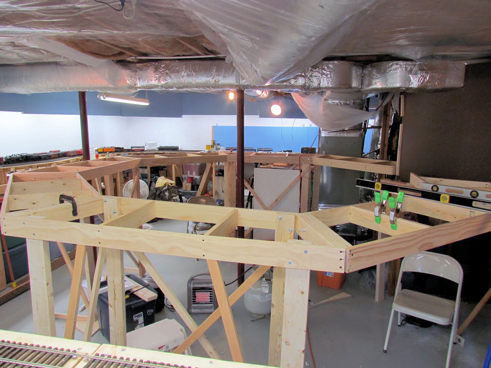
Here are pictures of the completed benchwork.


Doesn't look that large in the pictures; but let me tell you this is a big puppy.

The octagonal benchwork that I designed (see previous post) worked out well. The scheme of using legs under only every other section works OK, but it's important because it allows me to duck under the benchwork into the center of the helix easily.

A disappointment arose after the benchwork was complete. A narrow aisle was created near the basement walk-out door that did not show on my computer-generated plans because I did not draw the edge of the benchwork in the plan. I had assumed that the 3+' between the helix and the track along the wall would allow for a normal width aisle. The aisle as-built is only 24" wide; that's not really a problem except that I wanted to keep the walk-out entry handicapped accessible. There is a way to get a wheel chair in, but it cannot turn and go through the tight aisle. However, the wheelchair-bound visitor can duck under the helix to get beyond the constriction. Not ideal, but workable.

Here are some pictures with the first level of sub roadbed assembled from the sections cut back in December.


The sub roabed, made from 3/4 inch plywood, is set level in these photos. It will be raised to the final grade, which will rise from left to right (i.e. counter clockwise), before track laying begins. Also before track laying begins, there's a little matter of a double crossover that needs to be completed.

Monday, January 16, 2012

Using Specialty LEDs Part 1

The following is an unfinished chapter in an e-book that I am writing about practical electronics projects for model railroaders. Stay tuned for the complete chapter.

Previous installments include:

Fun with LEDs

Fun with LEDs II
Fun with LEDs III

This chapter builds on the ideas and demonstrations in the previous ones, so if you are not savvy with LEDs, you may want to read these first. If you are knowledgeable about LEDs, you may find those and this installment to be old news.


Using Specialty LEDs


(c) 2011-2012 T. Terrance

There are a number of specialty LEDs and LED strips that are available that can be useful for model railroads. There are LEDs that flash, flicker, display red/green/yellow in a single LED; as well as tiny 'surface mount' LEDs and LED lighting strips, both in many colors. This chapter will show you how to work with some of these LEDs and along the way you'll have enough knowledge to build the electronic guts of a Flashing Rear End Device (FRED), maybe a model campfire or two as well as light passenger cars.

Flashing LEDs

Flashing (blinking) LEDs are available from many sources: Miniatronics 12-130-03 and other numbers; All Electronics CAT# LED-4; Radio Shack 276-312; Mouser and Digikey have too many part numbers to list here. Use their on-line product selectors search for keywords 'flashing' or 'blinking'. Flashing LEDs are usually found in red, green, blue, yellow and white. When selecting a flashing LED look for the operating voltage (usually 3-3.8 VDC), the current requirements (in milliamps) and the brightness in millicandellas (mcd); although there is a workaround for a dim flashing LED as we will see.

Flashing LEDs have a built-in 'chip' that makes the LED flash. The next photo shows the chip inside of a translucent yellow flashing LED.


Using most flashing LEDs is simplicity itself. Simply hook the LED up to 3V DC, observing the proper polarity, and they begin flashing - no resistor is necessary if you run them on 3V. Here's a photo of three flashing LEDs in a simple test setup.


In the front is a flashing red LED from Lumex (Mouser part #696-SSL-LX5093BSRD, Lumex part #SSL-LX5093BSRD), next is a yellow flashing LED also from Lumex (Mouser part #696-SSL-LX5093BYD, Lumex part #SSL-LX5093BYD); both of these LEDs were salvaged from another of my projects and have had their leads cut short. The LED in the back is the aforementioned All Electronics flashing red LED. The LEDs are plugged into a 'solder less breadboard' which is a gizmo electronics geeks use to quickly make up test circuits without soldering. 3VDC is being brought in on the red and black wires to the rear. The photo caught the All-Electronics LED flashing while the others were off.
 
Here's a video of those LEDs in action, first with the room lights on and then, from a different angle, with lights off.


One thing that you will notice is how feeble the yellow LED is compared to the red. This is normal, red is usually brighter than the other colors; pay attention to this if you are ordering colors other than red from Mouser or Digikey where you may have many flashing LEDs to choose from.

Most flashing LEDs flash at a rate of 1 1/2 to 3 times a second. This may be too fast for some model railroad applications. Can they be slowed down? Yes they can. By dropping the voltage these LEDs will flash at a lower rate. The flash rate will go down as the voltage goes down below the nominal 3 VDC. The rate at which the flash declines is not linear, that is in the first volt below 3 VDC, the flash rate slows down quickly. The flashing will stop altogether at about 1.5 VDC. Here are the flashing red LEDs from the first video clip (All Electronic (to the rear) and Lumex) flashing at 3 V, then 2 V (11 sec. into the video) and finally at 1.7 V (19 sec. to the end).


You'll notice that as the voltage drops, so does the brightness of the LED. Without going into theory, this is to be expected. But can this be fixed? Yes, in two ways. You can start with a brighter LED; then as the voltage drops the brightness will drop too, but it may still be bright enough to be usable. The problem with this is that the selection of blinking LEDs is rather limited and you may not find one bright enough for your needs.

The other way is to put another, brighter LED in series with the flashing LED. Another LED in series with the blinking LED will flash in sync with the flasher LED. (See
Fun with LEDs
for an explanation and demonstration of LED series circuits). The selection of super bright LEDs is large and growing, so this method allows you to flash a super bright LED.

In the next video clip the dim flashing yellow LED from Lumex is wired in series with a high-brightness yellow LED with a clear lens. You see the LEDs flashing in sync with the room lights up and then in the dark.


If you remember from the previous installment, LEDs in series require a higher voltage than a single LED. The flasher LED requires about 3 VDC, a regular yellow LED requires about 2 V therefore we would expect that the combination would require 5 VDC to make it work; and indeed the demonstration that you saw above was running on 5 volts. Neither LED would light nor flash below 3.8 VDC. If you need to flash more than one additional LED, then the voltage required to run the circuit will increase about 2 V for each additional LED.

If you reduce the voltage to the series-wired LED+flasher the combination will flash more slowly; as the following video demonstrates.


In this video the red Lumex flashing LED is wired in series with a super bright red-orange, clear lens LED. The combination is running on 3.6 VDC. Compare the flashing rate with the video immediately above to see the effect of reduced voltage.

By the way, in the example above I've paired yellow flashers with yellow LEDs and red flashing LEDs with other red LEDs. However, the color of the flasher and the color of the LED that you put in series with it is totally independent, you can pair any combination of colors. This allows you to flash LED colors that do not come as flashing LEDs. The LEDs need not be of the same size either; the flashers that I have used are all 5 mm size (other sizes are available) but the series LED can be any other size, including surface mount LEDs. This allows you to flash surface mount LEDs which are not manufactured as flashers.

Are there other ways to flash an LED? Yes there are, but for simplicity the self flashing LED is hard to beat. When I write the chapters on building electronic kits and 'rolling your own' circuits, LED flashing circuits will figure prominently. At that time I'll talk about alternate flashers as are needed for grade crossings.

At this point you have enough information to make stationary flashers for most any scenery purpose, e.g. towers, advertising signs, bumpers, police and fire apparatus, etc. However, your power source needs to be low voltage DC. The easiest way to get pure DC is, of course, to use a battery. A pair of 'D' size batteries (3V) will power one of these flashers continuously for a year (I've actually done this experiment). If all of your LEDs are self-flashing, then wire them in parallel to 3V. If you have series strings of flashers and regular LED's, add more batteries to increase the voltage, as mentioned above. Hide the battery holder beneath the scenery and add an on/off switch and it will be a long time between battery replacement.

If you want to run your flashing LEDs from an rectified AC source, that includes any DC output of a power pack, 'wall wart' DC transformers, or a transformer/rectifier combination, you must follow some additional steps. First, you'll need to determine the polarity of the output terminals with a multi-meter as they are rarely marked. Next, the voltage is likely to be around 12V, especially using the fixed DC output from a power pack. Since the output of most power packs (as well as DCC and 'wall warts') is higher than 3-5 VDC you'll need a resistor in series with the LED(s) to drop the voltage a bit. Start with 1500 ohms and adjust up or down based on the brightness and flashing rate that you get. Most flashing LEDs will work fine with just a resistor to limit the current/voltage. Try this arrangement first and if it works, yuu can skip down to beyond the next couple of pictures. However, if your LED does not flash it may be that it does not like unfiltered DC. If your LED doesn't flash or is on constantly, you'll need to add a filter capacitor to the power supply output.

There are many different type of capacitors, (BTW, "cap" is used as shorthand for capacitor) the ones typically used for filtering are called 'electrolytic' capacitors. The key feature of electrolytic capacitors, for our purposes, are that they are polarized, that is they have a positive and a negative terminal; and must be hooked up with the proper polarity.

Capacitors are characterized by two values: their capacity (i.e. how much charge they can hold) and their voltage. Capacity is measured in microfarads (abbreviated uF). To filter a power supply for a reasonable current draw between 1/2 and 1 amp you'll need at capacitor between approximately 5,000 and 10,000 uF. As for voltage, a 35V or 50V cap should suffice. If you have a capacitor with higher capacity or higher voltage, it's OK to use.

Radial capacitors (that is, capacitors with both leads coming out of the same end of the device) can be obtained from: All Electronics (4700 uF, 65V, $1.65); MCM Electronics #31-5120(6800 uF, 35V, $5.14); Mouser #647-UVZ1V682MRD (6800 uF, 35V, $2.66); Mouser #647-UVZ1V103MRD (10,000 uF, 35V, $3.27); among many, many other sources. These types of capacitors are commodity items; so select one based on availability and price.


2200 uF, 35V Radial Electrolytic Capacitor

Filtering the power supply is straightforward. Attach the positive terminal of the cap to the positive output and the negative terminal to the negative output. That's it. Here's a video of a 1980's vintage MRC Tech II 2500 power pack with a filter capacitor on the fixed DC outputs running a flashing LED.


For this demonstration I've simply inserted the capacitor's leads under the fixed DC output terminals, observing the proper polarity. The resistor next to the flashing LED is necessary to reduce the approximately 12V output of the MRC 2500 to a value safe for the LED. This resistor is 1500 ohms, the value will be more to slow down the flashing rate. The value of the resistor will be less if you want to run a series-connected string of LEDs+flashers.

Now that we've discussed stationary flashing LEDs, what do you have to do to put a flashing LED into a car or locomotive? The simplest thing to do would be to battery power your mobile flashing LED. If you have space for a couple of 'AAA' batteries for 3 VDC (or four AAA batteries producing 6VDC for a series circuit) and an on-off switch you will not have to worry about reversing polarity on the rails, DCC square waves on the rails, over voltage or anything else. A battery-powered flasher will also flash when track power is off. AAA batteries will last a long time in this application.

If you must power the flashers from the rails then a rectifier and resistor will be necessary, as was demonstrated in the first installments (see Fun with LEDs II ). One additional component will be required to make the circuit function correctly; that component is a Zener Diode.

In a mobile application, the flashing LED may see as much as 18V from the rails and the chip inside of the LED needs to be protected form that high of a voltage. In addition, the use of a zener diode will allow you to have some control over the flashing rate by adjusting the voltage that the blinking LED sees.

A Zener diode is a special kind of diode which allows current to flow in the forward direction like a regular diode, but will also permit it to flow in the reverse direction when the voltage is above a certain voltage known as the breakdown voltage. When connected "backwards" (that is with its cathode connected to the positive voltage and its anode connected to the negative voltage) the zener will not conduct until it's breakdown voltage is reached. At or above the breakdown voltage the zener conducts and this trait can be used to limit the voltage that the flashing LED will see.

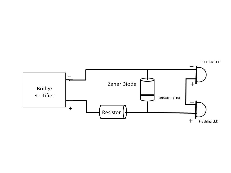
To accomplish this we put a zener diode across the + and the - after the resistor, but before the LED(s). The diagram below illustrates the set-up (click on the picture for a larger view).


I've drawn this with two LEDs, if you want just one, just ignore the second. The cathode (negative end) of the zener is marked with a black band. It needs to be hooked up to the POSITIVE side of the circuit. The circuit works in this way: As the voltage from the track starts to rise, the LED(s) will begin to flash. When the voltage exceeds the zener's voltage, it will begin to conduct allowing current to flow from + to -. Once it starts to conduct, the voltage in the circuit will not rise beyond the zener's voltage. And, by the way, the flashing will be at a constant rate after the zener conducts and limits the circuit voltage.

It is imperative that the zener's connection point occur after the resistor. The resistor in this circuit limits the current through both the LED(s) and the zener. If the zener is placed before the resistor, when the zener conducts too much current will flow and the zener will burn out.

Zener diodes are characterized by their breakdown voltage and their ability to handle current. For any reasonable string of LEDs used on a car or locomotive, a 1/2 watt (500 milliwatt) zener should be sufficient. 1, 2 and 3 watt sizes are also available, although they can get physically large. Use the table below to select the proper zener voltage.


Flasher alone
Flasher + 1 LED
Flasher + 2 LEDs
Normal flash rate
3V
5V
7V
Slow flash rate
1.8
3.8
5V


These zener values are suggestions, your LED or combination of LEDs may require a higher or lower voltage zener. Zener diodes usually do not come in even integer voltages, they will be something like 3.1V or 5.2V. Choose the value that you can find nearest to the ones in the table, getting the exact value is not necessary. Radio Shack has only 2 zeners (5V & 12V). NTE Electronics also has individually packaged zener diodes which can be found in stores dealing with electronic components. Mouser and DigiKey have a wide selection of zeners.

Here, I've built a mobile version of the flasher with a zener diode. This photo shows the rectifier, resistor and zener:


The cathode end of a 5.1 V zener is connected to the positive side of the circuit beyond a 1500 ohm resistor. the white wire is carrying the positive current to the remotely mounted LEDs and the blue wire is carrying the negative current.

Two series-connected LEDs are at the ends of those wires. One is the yellow flashing LED (Lumex) and the other is a 1.6 mm red, clear lens LED like the one in the next photo:


This tiny LED is small enough to be a F.R.E.D. in just about any scale including 'N'. Here's a video of both LEDs running on DCC track power (square-wave AC).


The yellow LED barely flashes while the tiny red LED shines brightly. This is just as well as the yellow flasher should be hidden with the rest of the circuitry.

If your flashing LED does not like the unfiltered DC that the rectifier outputs, then a small electrolytic capacitor will have to be added to the set-up.

As the final demonstration in this installment, here is a variation on the flashing LED, the flickering LED. These LEDs are found in LED "Tea Lights"; I bought mine at a dollar store 3/$1.


However, if you cannot find these tea lights near you, Electronic Goldmine has the bare LEDs: Flickering LED.

Here's a video of a flickering LED extracted from a dollar store tea light. First just the LED with its silicone-rubber candle top, then the flickering LED in series with a regular yellow LED.


Extracting the LED from the tea light is straightforward. Everything that applies to flashing LEDs applies equally to the flickering LED; voltage levels, series circuits, etc. A few of these hooked up to yellow, orange and red LEDs should make a convincing campfire. Especially if the LEDs were tiny surface mounted LEDs; but surface-mount LEDs are a story for another installment.

The next installment will deal with bi-color LEDs.

Monday, January 9, 2012

That Was The Year That Was

2011 was a pretty good year; in spite of getting off to an inopportune start. The year began with my first Open House for the Baltimore/Washington O Scale group on Jan. 8. A flurry of activity during the Christmas week just past had brought the layout to just about 70% of the way around the walls of the basement; not much to show for 3 1/2 years of construction.

Jan. 8, 2011 saw a light snow on the ground here in Virginia which deterred several people from attending (snow in any amount usually shuts things down here in VA). To make matters worse, a careless driver went whipping around a turn in the slick snow, couldn't hold the turn, crossed the line and wiped out my wife's car as she was on the way to pick up the 6' sub for our lunch! 2011 was off on a bad foot.

Despite all of that 11 people attended the Open House and I believe that a good time was had by all.

About mid-year the previous year, I had an idea for staging tracks and a reverted loop that I had not included in the original plans; but, if they were to be built at all, it had to be done before the main line progressed too much further. Building what I came to call hidden staging took a lot longer both before and after the the open house than I had anticipated. The first trains were not ready to run in hidden staging until the latter part of July 2011 (Aargh!) see First Train Runs in Hidden Staging.

From there on out, it was preparation for my second open house which I had committed to for Sept. 10. In the couple of weeks leading up to the second Open House I put in the Tray Run Viaduct trackage and almost all of the rest of the Cheat River Grade. (see Work On The Mainline Resumes and More Progress and T Minus 5 and Counting and D-Day). Nothing like a deadline to concentrate your efforts.

After the open House, the Cheat River Grade backdrop went up; see A Backdrop for the Cheat River Grade. Finally, the year closed out with construction beginning on the helix; see Construction of the Helix Begins.

Between all of this I produced three instructional videos (Fast Tracks Tips and Techniques, Install a DCC Decoder in a Brass Steamer, Photo Backdrops Made Easy) several smaller videos and several instructional postings; had my first published article and appeared on many episodes of Model Rail Radio. And, oh yeah, my day job was pretty demanding as well.

Although I would liked to have done more, 2011 has been my most productive year. Looking forward to 2012, I want to complete the helix and at least one track on it by my next Open House, Apr. 21. After that, I hope to have the golden spike ceremony for completion of the main line by the end of the year.

Wish me luck.