M&K Junction Railroad

M&K Junction Railroad
Another train of eastbound coal crosses the Cheat River

Tuesday, November 8, 2011

Fun with LEDs

The following is an unfinished chapter in an e-book that I intend to write about practical projects for model railroaders. I'm publishing it now because on one of the forums the participants asked for an LED primer. Stay tuned for the complete chapter:

Fun with LEDs
Text and Photos (c) 2011 T. Terrance

Light Emitting Diodes (LED) are ubiquitous in the modern world. They have all but replaced the miniature incandescent lamp. In the hobby of Model Railroading it is hardly any different. Most recent locomotives come equipped with LEDs for lights; as do some signals, accessories and structures. LEDs are available in a wide range of colors and sizes. If you are planning to illuminate anything on your railroad, you might want to consider LEDs. This chapter will give you the knowledge to do so. If you are an old hand with LEDs you may want to skip what follows.

An LED is simply a small chip of semiconductor material that can emit light. It does this very efficiently and therefore uses very little current and emits little heat. The chip is encapsulated in a dome-like housing with a flange made of clear or translucent epoxy resin. Two leads protrude from the housing, a positive one called the anode and a negative one called the cathode. The following figures shows a typical LED, and the arrangement of its internal components and its schematic symbol (don’t worry, you don’t really need to know the latter two).


Schematic diagram of an LED:


The epoxy covering can be clear (sometimes referred to as “water clear”) or in one of many colors: red, green, yellow, blue and white being the most common; but amber, orange, pink, violet, warm white as well as invisible infrared and ultraviolet are available. The covering can be frosted (called diffused). The color of the LED is inherent in the chip, not in the coloring of the epoxy. The brightness of LEDs is usually measured in millicandellas; the more millicandellas the brighter the LED is.

Specialty LEDs that flash, flicker and alternate between colors are also available (more on those in another chapter).

LEDs come in a variety of sizes and shapes but in this chapter we will concentrate on the 5mm round (T 1 3/4 size), 3mm round (T1 size), 2mm round and square (T ¾ size) and below as the most useful for model railroads. These are readily available sizes. We will talk about “chip” LEDs in another chapter.

Nowadays LEDs are commodity items and many times you do not know who the manufacturer is; as in the LEDs bought from Radio Shack (no, Radio Shack does not manufacture them). This chapter will use commodity LEDs except where a special characteristic is required, then I will call out a manufacture’s part number and a supplier.

Enough of this background information, let’s get down to what makes LEDs different from regular bulbs.

1. LED’s must be powered with DC; bulbs don’t care.
2. LEDs must be hooked up properly to the positive and negative voltage; bulbs don’t care.
3. LEDs are sensitive to current and will fail rapidly and suddenly above a certain current.
4. Strings of multiple bulbs should be wired in parallel, stings of LEDs should be wired in series.
5. Regular bulbs get brighter with higher voltage until they burn out; LEDs get brighter with more current up until the current where they fail.
6. LEDs can last in excess of 50,000 hours.
7. LEDs can be switched on and off repeatedly without decreasing their life.
8. Small LEDs do not generate significant heat.

Items 1 - 4 are the key characteristics for working with LEDs. 5, 6 and 7 are nice to know, but do not affect how you work with LEDs. If you are lighting a wood or cardboard structure, knowing 8 comes in handy.

Characteristic 1 – LEDs must be powered by DC because they are a semiconductor device and not a glowing filament. There are ways to power an LED from AC with the addition of external components, but they have the net effect of rectifying the AC to DC for the LED. Remember, DCC is a form of AC so an LED cannot be connected directly to a DCC track output either.

Characteristic 2 – LEDs must be connected correctly to the positive and negative voltage to work properly. Not only to work properly, but even to survive. If an LED is hooked up backwards, and the voltage is high enough (say, above 6V) failure of the LED can be instantaneous. The following figure shows how to identify the anode (positive terminal) and cathode (negative terminal) of a typical LED.
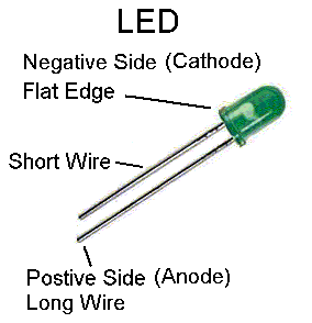


The cathode (negative) is the shorter wire and the epoxy housing has a flat edge on the flange next to the cathode (rarely it’s not a flat edge but a notch in the flange). The longer wire is the anode (positive). The flat in the flange allows you to identify the cathode even after the leads are cut short to install the LED. But you cannot just hook up a battery to the LED which brings us to...

Characteristic 3 – LEDs are sensitive to current and will fail above a certain current. OK, we have to talk about some theory here. When a diode, any diode including LEDs, is hooked up with the positive terminal attached to positive voltage and the negative supplied with negative voltage a current will flow through the diode. That’s what diodes are designed to do, they are a one-way valve for electricity. A diode will allow a LOT of current to flow, in fact, it appears as almost a dead short. Some diodes can handle large currents, as in the diodes used in rectifiers. The small LEDs we are dealing with here, however, can only pass a very small amount of current without burning up; typically 20-25 milliamps (25 thousandths of an amp). If you just hook up an LED to a voltage source a LOT of current will flow and the LED's life will be VERY short indeed.

To prevent burnout we need to limit the current flowing through the LED to a safe level. This is accomplished with a resistor. A resistor, as the name implies, restricts (resists) the flow of current. A resistor in a series circuit (i.e. in line with) with another device will limit the current flow through the device. To choose the value of the resistor we use one of the fundamental relations in electronics – Ohms Law.

V/I = R

In the equation above, I have written Ohms Law to find the resistance (R) for a voltage (V) and current (I). For example, if we are using 12 V, and desire a current of 25 milliamps (0.025 amps) then...

12/0.025 = 480

So a resistor of 480 Ohms will result in a current or 25 milliamps (ma) at 12V.

If you don’t care for the math, or just want a quick reference, here is a table of common values to produce 25 ma.

Voltage

Calculated Resistor

Value (Ohms)

Nearest “Standard”

Resistor Value


3 V/3.3V

120

150

5/6V

240

270

9V

360

390

12V

480

470

15/16V

640

680

18V

720

1000

24V

960

1000


The calculated resistor values are not readily available as ‘standard’ resistor values, so column 3 has the closest resistor that you are liable to find in an electronics store. In almost all cases the resistance value is higher, therefore the current will be lower; but this will not significantly effect the output of the LED. If this table is still too much to comprehend, use this rule of thumb: for most model railroad applications use a 680 ohm resistor – you won’t be too far off.

Drawings of small resistors and the resistor’s schematic symbol are reproduced below.


Notice the color stripes on the resistors. They tell you the value of the resistor. Rather than go into a tutorial on the resistor color code, I will call out the stripes on any resistors that we will use. If you are interested in the resistor color code you can look it up using on-line resources. Here’s a particularly good resource that has tables of resistor values and their corresponding color codes: Resistor Col
or Charts

Now we can begin lighting up some LEDs. We’ll build the following test circuit using an LED (any color will do), a 270 Ohm resistor (Radio Shack 271-1112 or similar), a 5-6VDC power source (5V power supply, 6V battery pack, or power pack track output [DC] set for 6V) and 3 alligator-clip test leads. The 270 Ohm resistor will have red-violet-brown stripes on it, in that order.

A schematic diagram of the circuit would look like this;


The end of the LED symbol with the vertical bar indicates the cathode (negative) end; and the side with the arrow head indicates the anode (positive) end. The circuit operates because electricity flows from the positive voltage (V+) through the resistor, which limits the current, thence through the LED causing it to illuminate and returns to the source of the electricity through the negative return line.

Here is a picture of the circuit laid out on my workbench.


Power is coming in from a 5V power source located off-camera to the left; red is positive. Next it’s connected to the resistor, which can be connected from either end, as it has no polarity. The positive current is then connected to the anode lead under the LED at the right. The black alligator-clip test lead is clipped on to the cathode of the LED (the one next to the flat). Thereupon it returns to the negative terminal of the power source. As you can see, the LED lights up

If your eyes are really sharp, you’ll notice that the color code on the resistor is red-red-brown, which makes it a 220 ohm resistor; since this is a 5V source, the current should be about 23 ma, so it’s safe.

This circuit, or one like it, can be used to illuminate structures, street lamps, car headlights, any stationary object where you can be sure what the polarity of the current is.

What if you need the light of more than 1 LED? LEDs can be connected in series strings, as shown in the next photo.


Power still comes in from the left on the red and black wires. But the circuit has been reworked to connect the cathode of the first LED to the anode of the next and so on, cathode to anode, until the last cathode is connected back to the power source. The single resistor limits the current flowing through the entire string.

The schematic diagram for this circuit looks like this:


This brings us around to characteristic 4 from the list at the beginning of this chapter.

Characteristic 4 – LEDs should be wired in series. When you wire bulbs, they are wired in parallel, that is, one wire from each bulb is connected to the positive and the other wire is connected to the negative. In this way, if any bulb burns out all of the rest stay lit. LEDs could be wired in this way, but each LED would require its own resistor to limit the current. Since LEDs with the proper current limit are unlikely to burn out, there is no reason not to wire them in series and use a single resistor for the whole string. That’s what I did above.

However, to pull off this trick we have to make an adjustment in the circuit. Each LED uses a little of the electricity as it passes through the device and this use of electricity results in a voltage drop. The voltage drop is about 2V for each LED; a little more for white LEDs and a little less for other colors, but 2V is a good approximation when you do not have the specific parameters of the LED. Therefore the string of LEDs in the photo above is not running on 5V, 5V would not be ‘strong’ enough to cause current to flow if each LED used 2V (4 x 2V = 8V drop). So I upped the voltage on the circuit to 12V.


Continued in Fun with LEDs II


Tuesday, October 11, 2011

We don't need to build no stinkin' scenery!

Scenery? Scenery? We don't need to build no stinkin' scenery!

I've been meaning to try this little experiment for a while. Could I 'green screen' (chroma key) scenery onto an otherwise bare layout? With the help of a green fold-up school project display board from Wal-Mart I believe the answer is - yes.

I took a few quick clips in front of the improvised green screen and with the help of Corel Video Studio I added a panoramic picture that I took in the valley of the South Branch of the Potomac River. While not perfect in composition or execution, it works for a quick first attempt. Judge for yourself, with and without digital enhancement:


Don't click on 'HD" to turn on Hi Def mode unless you have a fast internet connection and a fast computer.

Of course there would be ethical questions surrounding doing this without full disclosure. But I can see the utility of using this technique to try out scenery treatments.

Wednesday, September 21, 2011

Curved Crossover

This curved crossover is in the lead into hidden staging. It was completed in the run-up to the open house and I did not have time to make a post to this blog. The turnouts are scratch built except for using the Fast Tracks Stock-Aid tool for the stock rails and the Point Form tool for the point rails.

The curved turnouts were made with code 156 rail from the old Atlas O scale flex track as the flex track either side of these turnouts be will be the old Atlas. Since these turnouts will, eventually, be hidden, I did not use as many ties as I would have for a turnout out in the open for the sake of economy.


Here are two pictures of the completed crossover with track connected to it. One servo-motor switch machine which had to be placed above the sub road bed as the points were directly above a joist.

Sunday, September 18, 2011

How to Convert Used PC Power Supplies for Your Model Railroad


The genesis of what follows was an article that I submitted to a magazine which was rejected. I reworked the article, but rather than resubmit it, I got the idea to build an e-book around it. So this will become chapter 3 of an upcoming e-book tentatively entitled
"Electronic Projects for Model Railroads Cookbook". Other than an outline, the details of what the e-book will look like and it's release date are still to be determined. In the meantime enjoy this preview.

How to Convert Used PC Power Supplies for Your Model Railroad
Text and Photos © 2010-2011 by Terry Terrance

O Scale locomotives can really eat up the amps. Dual motors, large consists, and open frame series-wound motors, it all adds up quickly; and that’s before you add long strings of lighted passenger cars! You need power, and lots of it. There are good, high output powers supplies available but they all share a common characteristic – high cost. Would you like to get upwards of 20 amps of clean 12 VDC current for little or no money? The power supplies from discarded IBM-compatible Personal Computers (PC) can be readily converted to supply pure, filtered, regulated DC to your model railroad. Once you have that power available, you can use it to run trains, throw switch machines, light structures, etc. Anyone with average mechanical and electrical skills can do this conversion – if you know how to use a multi-meter, you can complete this project!

The power supplies found in PCs are known by an array of designations: XT, AT, ATX, WTX, and so on; and come in a variety of sizes (see Photo 1). While all of this is standard fare for your neighborhood computer geek, there are only two characteristics that we will need to know to start our conversion.
Photo 1
The first is how much DC power can we extract for our railroad? PC power supplies are rated by the total number of watts that they can deliver; anything from 65 watts to over 1000 watts. However, all of that power is not available as any single voltage, it’s distributed among all of the voltages produced by the supply such as +3.3V, +5V and +12V. Why this is important will become clear shortly. Photo 2 shows the labels from the four units in Photo 1; with ratings between 90 watts and 400 watts, their output ranges from 4.2 amps to as much as 30 amps of the three main voltage outputs.


Photo 2

Notice that the label in the lower left of Photo 2 also contains the wire color code for the various voltages; keep this handy to refer to.

If you need +12V to run a conventional DC layout, then the +12V output will be of the most interest to you. However, +5 VDC can be used to power servo motor switch machines and +3.3 VDC can be used for layout lighting with LEDs. 12 VDC (or +12 VDC & -12VDC) can be used to run Tortoise slow-motion switch machines.

However, most DCC systems will not run on 12V but require more, with 15V being the usual minimum. Unfortunately, you cannot connect the +3V or +5V in series with the +12V to get a higher voltage, the design of these power supplies is such that all of the grounds are common to every voltage and connecting any + to any – will result in a dead short.

Nor can you connect the outputs of two separate supplies in series to get a higher voltage. Most of these switching supplies are designed with the output ground common with the 115V mains ground, creating a sneak path through the wall socket that creates a short if two supplies are connected in series.
What else do we need to know before we hunt down some used PCs for their ‘ivory’ (i.e. their power supplies)?

You’ll need to know what generation of PC supply that you’ve salvaged. This is important to getting the supply to turn on. You can tell the generation by the type of connector that attaches the power supply to the main board (motherboard) of the donor computer. Photo 3 shows the connectors used in the first few generations of PCs. A power supply with these connectors will look like the large supply in the center of Photo 1.

Photo 3

These units are also characterized by a large on-off switch on the side. Early supplies like this are turned on with this switch, unlike subsequent generations of supplies, as we will discuss later.
Photo 4 shows the motherboard connector used in the next generation of PC supplies.

Photo 4

These use a 20 pin motherboard connector. These supplies are smaller, like the gray unit on the upper right in Photo 1, and, generally, produce more power.

Photo 5 shows the latest generation of connector. It has four additional pins, including an additional 12V circuit; otherwise it’s like the one in Photo 4.


Photo 5
If your motherboard connector does not match anything in photos 3-5, you probably have a non-standard, proprietary power supply. I'd bet that this supply came from a computer made by a major manufacturer (Dell, IBM, HP, Compaq, etc.) who  probably wants to force the consumer to buy replacement parts from them.  These supplies still put out the same major voltages (+3.3V, +5V and +12V) but they may do it on different pins or using a non-standard color code.  If you are lucky, the label will have information that will enable you to figure this out; most likely not, however.  If you are handy with a multimeter and using the instructions here as clues, you may be able to figure it out for yourself.   Otherwise, find a different used power supply.

Let’s begin the conversion.

Step 1: Find a used PC. You may already have an unwanted PC or two; but if you don’t, many municipal refuse dumps now have a section where PCs and other electronics are ‘recycled’ to prevent the lead in their solder from winding up in the dump. If your town lets you pick over the pile, you’ll have your choice. A tip here is that name-brand PCs (e.g. Dell, IBM, HP, and Compaq) will have quieter fans; but these manufacturers are so cost conscious that they often have power supplies tailored to the exact model of computer they will be built into, supplying only the minimal power needed to run those machines. And they may also have proprietary connectors that will not follow the procedure that we will use to rewire the supply (Compaq was notorious for this).

You may also want to avoid the smaller, ‘small form factor’ PCs – small machines typically have underpowered power supplies.

Another source of used PCs is garage sales. You can even wait until the sale is over, it’s very likely that an old machine will not sell and will be discarded; nothing is less desirable than a four year old computer. Goodwill and the Salvation Army sometimes have used computers for sale. Do not pay more than $10-15 for a used PC as you can often buy new PC power supplies on sale for $15.

Good hunting.

Step 2: Identify and extract the power supply. PC cases come in too many configurations to describe here, but “desktop” and “tower” cases are common variants. Most will have some hex-headed, Phillips screws around the periphery of the back that, once withdrawn, will allow you to remove the top. Some ‘tower’ cases have a single removable side. Remove the top (or side), and the power supply will be against the back wall of the case (Photo 6).

Photo 6

Look at the label on the supply if it’s visible. If the capacity of the supply is low (say, less than 5 amps on 12V or 5V) and you obtained the PC for nothing, you may want to consider throwing this ‘small fish’ back and trying again.

Next, extract the power supply. The supply will be held in the case by, typically, 4 Phillips screws on the back of the case. These screws will be arranged in an irregular pattern on the back of the supply. The circled screws in Photo 7 show the most common arrangement.

Photo 7

Do not remove the four screws closest to, and arranged in a square, around the fan. Removal of these screws will cause the fan to come loose inside the power supply (Photo 8).

Photo 8

If you do withdraw all four of these screws and the fan does come loose, DO NOT go into the power supply case to reattach it.
These power supplies generate lethal voltages in excess of the line voltage that can linger long after the supply is turned off. Do not open the case of one of these for any reason. You’ll see this same warning posted on the label of the supply too.

Step 3: What power supply do you have? Start detaching all of the power cables that come out of the supply that are attached to the various units within the computer like disk drives, etc. However, save the big connector attached to the large circuit board (motherboard) for last. Photo 9 illustrates a typical installation.

Photo 9

Pull this connector and compare it to Photos 3-5. Remember which configuration that you have as it will guide you through the next steps. If your main connector(s) do not match one of the configurations above, including the colors of the wires, then you may have a proprietary power supply; you may want to try another donor computer.

Step 4: Power up and test.

4a) If your motherboard connectors match Photo 3, plug a computer power cord (i.e. an IEC cord) into the matching receptacle on the back of the supply, plug it into the wall and flip the big switch on the side of the supply. The fan should come on when the switch is turned on. Use a multi-meter to measure the DC voltage between any black (gnd) wire and any red (+5V) wire; record the results. Next measure the voltage between any yellow (+12V) wire and any black wire; record the results. You may want to clip and strip the ends of the black, red and yellow wires to read the voltages. If the black-red voltage is between approximately 4.75 and 5.25 volts and the black-yellow voltage is between approximately 11.4 and 12.6, congratulations! You’re almost done, go to step 6. If the fan does not come on, or the voltages are outside of these ranges then go to step 5.

4b) If your motherboard connectors match either Photo 4 or Photo 5, you need to take an additional step to get your power supply to turn on. Take a paper clip, break out the small ‘U’ shaped piece in the center and insert it into the connector to short out the green wire and the adjacent black wire (see Photo 10); you may have to shorten one or both legs of the ‘U’ to get it to fit down inside. What you are doing is mimicking the ‘power on’ signal from the motherboard. Repeat the steps above, insert the power cord, etc., but use the small rocker switch on the back to turn on the supply. If the fan does not come on, check the shorting jumper between green and black. If the black-red voltage is between approximately 4.75 and 5.25 volts and the black-yellow voltage is between approximately 11.4 and 12.6, go to step 6; otherwise go to step 5.

Photo 10

Step 5: What gives? The fan does not turn on; or I get no voltage; or the voltages are out of range.

5a) If your power supply connector matches Photo 3 and the fan does not turn on, or you get no voltage, recheck all of your connections; make sure that the wall outlet has power; check your multi-meter against a known voltage source (is your meter set to read DC?); try different black, red and yellow wires; clip and strip the black, red and yellow wires to guarantee good connections to your meter. If you still get no output, it’s very likely that the power supply is dead.

5b) If your power supply connector matches Photo 4 or 5, then do all of the steps above plus recheck the green-black shorting connection. Try shorting the green to any other black wire. Clip and strip the green and black wires and twist them together. If you still get no output, suspect a dead or non-standard supply.
5c) If the fan is on but the voltages are significantly out of range, or there is no voltage output at all, it may be because the supply needs an electrical load to function properly. Without going into a lot of theory (and making your head hurt), unlike the linear power supplies that we usually deal with containing a transformer, rectifier, etc., these ‘switching’ power supplies use the load as part of the regulation circuit and may not produce voltage if there is no load. I would not consider a voltage out of range by a couple of tenths of a volt either high or low as a serious issue. This would be an issue for a computer, but not for a model railroad. But if your voltage is way out of tolerance, you have a couple of choices.

Do nothing; your voltage may be a little low (or high), but it may make no difference. This is an option if you have a truly conventional DC operation with rheostats, etc.; after all, how often do you run at maximum speed? Nor will an over/under voltage condition effect the operation of lights, servos or Tortoise switch machines, so long as the voltage is not grossly out of range.

The other alternative is to provide a load in the form of a power resistor. You’ll have to go this route if the supply is producing no voltage whatsoever. A power resistor is not the little dog-bone shaped component that you find in most electronics, but a large, robust, wire wound, ceramic or metal encapsulated device (Photo 11). The power resistor will provide a constant load the moment the supply is turned on and the output voltage should always be present and within tolerance.

Photo 11

I have had good results with a 2 ohm, 15 watt or more, resistor (e.g. Allied Electronics stock #895-1334 or #296-4380) soldered between a red and a black wire. Clip a red wire (+5V) and a black wire from one of the disk drive connectors (Photo 12) and solder the resistor between them; insulate the connections. We’re doing this on the +5V line because there’s always more +5V available to waste. Be careful where you mount this resistor as it will get HOT. By putting this in a disk drive line, you’ll have enough wire free to mount the resistor in the airflow of the fan to keep it cool.

Photo 12
By the way, the voltage on these power supplies will wander a bit under load, but should stay within or near the voltage ranges given in step 4.

Step 6: Getting ready to power the layout. If you’ve gotten here, you have your PC supply working – good job!

If you used the paper clip to get your supply to turn on, you have a few choices. Leave the clip in place, secure it and insulate it with electrical tape; or cut the green and black wires and solder together permanently; or attach a SPST switch to the green and black wires. Doing the latter will allow you to mount the switch remotely and use it to turn the power supply on and off.

If you are going to be drawing a heavy load on any of the +12V, +5V or +3.3V power. Collect a number of the yellow wires (+12V), red wires (+5V) or orange wires (+3.3V) together from the main connector and the disk drive connectors on the supply so that no single wire is trying to supply the whole load. If you have a 24-pin main connector (Photo 5), be sure to use all of the yellow wires from the main connector to get the maximum capacity of +12V. Tie together several black wires to handle the return current.

Which brings us to an important safety issue:

These supplies are capable of providing very heavy currents on +12V +3V and +5V, therefore all circuits attached to these supplies MUST be fused.
25 amps at 12V (300 Watts) surging into a short circuit is enough to weld rail, melt wires, weld wheels, melt ties – and start fires. These power supplies are supposed to be manufactured with built-in current limiters. However, these current limiters will allow more than 18 amps to flow before they shut down. This is set too high for model railroad use. Break up your power system into the smallest circuits feasible and fuse each of  them for only as much current as you will normally use. For instance, if you will be running two throttles and each can draw 10 amps, fuse each throttle for 10 amps rather than fusing the 12V for 20 amps. Fuse each positive voltage separately. Do not put the fuse in the common ground return line as the sum of the currents may cause blown fuses. Fuse blocks for AGC glass fuses and in-line fuse holders for automotive-style blade fuses are available at auto parts stores and Radio Shack –

Do not fail to use them

Similarly, use wire of sufficient capacity for the expected currents. American Wire Gauge tables found on-line rate the current carrying capacity of 16 ga. wire as 3.69 amps and 12 ga. as only 9.33 amps! If you are going to be switching heavy loads, you can find 35 and 50 amp toggle switches at your local auto parts store
.
Finally, if you are using a power resistor to load the supply, mount it to the case, or in the airflow of the fan, or to its own heat sink.

Enjoy the luxury of having more power than you will likely need.


Saturday, September 10, 2011

D-Day

Well my open house has come and gone and I judge it to be a success; but first the back story.

Friday night I was still making some electrical connections in hidden staging. When I was almost finished, I discovered a short where there should not have been one - and it's now 10 pm. This time I restrained myself from ripping out the just completed wiring and did some troubleshooting with an ohm meter. There was a short sure enough, but the circumstances were such that it could not have been the wiring that I had just put in. Long story short - some straps on a turnout that I had installed had not been removed - my bad.

Saturday morning I discovered, much to my chagrin, that my B&O B-18 Ten Wheeler was picking the turnout into what will be Alpha Portland Cement (See the Curved Turnout 4/26/10). This could not have been discovered heretofore as this switch was the end of track before last weekend. When the loco went through trailing-point style, it was fine. When the loco tries to go through facing-point it picks the switch every time. Rolling stock goes through fine in both directions. Well, no time to diagnose it before the guys show up, I'll just have to warn everyone about it.

People showed up in dribs and drabs until there were 8 guests. Everyone had an opportunity to run trains, although not everyone availed himself of it.

During my last open house, through my own oversight, I took no pictures during the event. This time I resolved not to make that mistake and I carried my camera around my neck - but I still took no pictures! I was so busy being the host that I did not have the bandwidth to get it done. The best that I could accomplish was some pictures during lunch and a group shot outside.


That's me, the guy who's out of uniform. It's not that strange that almost everyone else is wearing a blue golf shirt as most of the guys have the shirts from hosting the 2004 and 2009 O Scale Nationals, and they usually wear them to train night.

My best performing loco, a Weaver die cast Pacific, which usually can crawl through the crossovers at M&K Junction was acting up, of course. However elsewhere on the track it would crawl like a champ, everyone was impressed.

The final faux pas of the day was that all of the DCC locomotives did not seem to be receiving the packets to reverse direction well. My guess is that the layout now has gotten so big that it cannot be handled from one command station/booster and more boosters are needed for the length of run. I have the boosters, and the layout is wired for them, but have been reluctant to take the time to put them in. I guess that I cannot put it off any longer.

Other than that, the track which had only been installed the week before and not given a thorough shake-down performed well and there were no derailments that were not caused by operator error (the B18 excepted).

My Fast Tracks jig-built turnouts were an object of some curiosity; although everyone agreed that they were very smooth running.

Special thanks to my good wife for preparing the cookout, including her homemade potato salad and cookies. I could not have pulled it off without her.

The next open house will be in the spring and, hopefully, I will have completed the central helix by then to allow for continuous running.

Monday, September 5, 2011

T Minus 5 And Counting

It's Monday night Sept. 5, Labor Day, and my layout tour is just 5 days away. I'm about a day behind schedule in what I planned to have ready and it looks like the temporary loop to connect the Cheat River grade with hidden staging is not going to get built. I have a busy week at work this week and I will not get back to the layout until Friday, at which time I will be cleaning up and making last minute electrical connections.

Here's a picture of where work stands in the central part of the basement:


New benchwork and trackwork has been added adjacent to the section completed last week. There are going to be two tracks on the section to the right, but only the one track shown will be ready in time for the 10th.

The future site of the Tray Run Viaduct now has track laid on it.


I'm really happy with the track alignment going onto the Tray Run Viaduct, this next photo of the track on the viaduct does not show the shallow 'cosmetic' curve leading into the bridge. I have not run any rolling stock through this track yet, it will get a trial by fire, probably Friday night.


The top of Cheat River grade is shown in the next photo. Since the temporary connection between here and staging will not happen prior to the open house, I will not finish this track to the very top of the grade before Saturday. I may add one more section of flex track to the upgrade (westbound) track on the left and call it quits for now.


The section of benchwork/track on the right in this next photo leads to hidden lower staging. The track in the picture will be the exit track from staging and another track will eventually be laid to the left of the one in the photo that will be the entrance track to staging.


I developed this track arrangement 'on the fly' as hidden staging was not in my original track plan. The graceful reverse curve that resulted is too nice to cover up; but it will be covered eventually. I also have not yet tested this reverse curve with rolling stock, especially passenger equipment, but I anticipate no problems.

Because there will be no temporary connection, for the open house the layout will operate as two separate sections. From the top of the Cheat River grade around the basement to about half way up Cranberry grade; this point is above the stub-end tracks of staging. The other section will be hidden staging and one of its approach tracks.

I've spent six full days over two weekends working downstairs and made tremendous progress but, because I have not done my usual routine of "planning" a project to death before building and then double and triple checking everything during construction, I'm not sure yet how all of this new construction will come out. If everything comes out OK then maybe I'll learn that I can work faster.

Sunday, August 28, 2011

More Progress

Nothing focuses your attention like a deadline. We've had an earthquake and a hurricane locally here over the last week, but the only thing that has been on my mind is my upcoming layout open house in two weeks.

So new benchwork has risen over the track arrangement that I lofted onto the basement floor last week.


The track plan was left on the basement floor as a guide for placing the benchwork as well as an aid in placing the subroadbed. I'll probably leave it there until the track is laid.

The left hand side of the benchwork is attached to the 2x4 supporting the stairs and to the adjacent section of benchwork; this section of benchwork has no legs supporting it. I'm going to try to keep this section clear as a 'crawl under' to get out of the dead-end aisle that is created at this section of the layout. When a crew brings a train to this point, the train will enter the central spiral which acts as serial staging and that crew's run is over. Therefore the the dead-end has no operational implications. But the crawl-under may be useful as a short-cut to get to the other side of what will be a double sided backdrop to retrieve a tool or a Coke.

Subroadbed was put into place next.


This part of the railroad is on the Cheat River grade which was literally blasted out of the side of a mountain. The subroadbed is on raisers so that on the aisle side of the track the scenery can fall away from the grade as it does in real life. the subroadbed is set level in this picture, as a next step I will raise the subroadbed to the 2% grade here. That will result in the subroadbed to being higher to the left as seen from this angle.

Here's a photo of a special piece benchwork under the straight subroadbed at the far end of the picture above.


This section of benchwork will be the future location of a model of the Tray Run Viaduct and in this area the scenery will extend significantly below the roadbed, almost to the floor.

Here's a picture of the real Tray Run Viaduct.


The Tray Run Viaduct is 443 feet long, has four 90 foot arches (the left most one is not visible in the 1974 picture above as the B&O has dumped fill over the side of the viaduct almost filling the easternmost arch), and stands about 105 feet high. I've been to this bridge; it's nestled in a deep and steep gorge and is a very impressive structure. My model will be about 65% scale size, making the model just about 6 feet long. Each of those exceptionally high track risers made out of 2x4 lumber will be one footing of an arch.

Right now all track risers and subroadbed in this section of new construction are held in place with clamps. When I adjust the subroadbed to final grade the clamps will be replaced with screws.

This new construction which intrudes into the center of the basement is the first departure from the around-the-walls route that has been the rule heretofore. It provides a hint of the involved benchwork/trackwork to come and really gives the feel that this is becoming a basement-filling model railroad empire.