M&K Junction Railroad

M&K Junction Railroad
Another train of eastbound coal crosses the Cheat River

Tuesday, July 24, 2012

Twins?


Well, not really; not as much as one would hope.

Like everything else there's a story connected with this.  Back on July 8 I hosted a model railroader at my layout.  I had had the brass Sunset Models B&O I-12 caboose on the left for some time, but had not put it out on the layout.  So I put on a pair of couplers (quite a task due to poor design) and put it out for the session.  With this caboose on the layout the converted 3-rail MTH caboose I had been using now looked very oversize. The MTH is a nicely executed caboose, but too large to be a B&O I-17.  So now that I was unhappy with the MTH I had to get better cabooses on the layout.  So I pulled out one of the Lionel B&O I-12 cabooses that I have and began the conversion from 3 rail to 2 rail.

The caboose on the right is the Lionel B&O I-12 converted to 2-rail.  Before I launch into the Lionel's shortcomings let me say this;  Lionel is to be applauded for mass-producing this caboose.  This is a prototype unique to the B&O and its successor the Chessie System.  Only 125 prototypes ever existed.  For Lionel to invest in such a limited application model is worthy of support.  I have bought 4 of these cabooses and, depending on how I resolve the shortcomings that I will talk about, I may well buy more.  What follows is more of a review with an eye towards helping produce better models than a condemnation of a flawed product.

Neither the Sunset nor the Lionel is a dead-on-accurate model.  The Sunset cost about twice what the Lionel costs, and that needs to be borne in mind.  Let's start with simple things like color.  Not even the B&O Yahoo group can agree on what paint represents an accurate red for B&O cabooses.  But all agree that it's a bright red.  On that basis, the Sunset is too dark.  I believe, looking at color photos of the prototype, that the Lionel may be a shade too bright; but the Lionel's color is the better of the two.  By the way, the white lettering on the Sunset, which is numbered for a first batch I-12 and Lionel's use of yellow for a second batch I-12 are both correct.

This brings me around to a minor beef that I have with all of Lionel's production.  Lionel marks all of it's models with the Lionel item number and "Built by Lionel"  as seen in the next photo.


Lionel does this all of the time.  It's unnecessary.  Lionel collector's will know that this was "Built by Lionel"  It's minor because I can Photoshop this out in pictures, but I should not have to.

There's one flaw on the Lionel that could be corrected, but to do so would require stripping the entire paint job and repainting.  Running through the center of the bay window on a real I-12 is a lap joint in the side sheet metal accompanied by a line of rivets.  The Sunset omits the lap joint entirely, as you can see below.


For some inexplicable reason, probably associated with language difficulties, overseas manufacturing or interpretation of drawings, the Lionel has a groove where the lap joint should be.


Maybe this was an honest attempt to represent the lap joint, but the groove is the worst aspect of Lionel's model.  It could be filled in with putty and sanded, but doing this so close to the line of rivets and having to repaint the model is more bother that I am willing to put up with.  I'll have to live with this one.

Speaking of rivets, Lionel's are sharp and stand proud of the sides of the model, Sunset's are pressed into the brass and somewhat indistinct.  Lionel's are easier to see with old eyes, and at a distance; you'll have to judge for yourself which is preferable. And, no, I don't know what the correct count of rivets should be; but on my next trip to the B&O Railroad Museum... :-).
  
Now for my observations about the Lionel trucks, which are horrid.  First, like many 3-rail models, the Lionel sits too high when on it's trucks.  Supposedly this is necessary to clear the 3-rail flanges and couplers.  However, the Sunset model was also available in a 3-rail version, yet it sits at a more prototypical height.  The height will also cause problems with coupler mounting.

The complex design of Lionel's truck (or MTH's or Atlas's similar trucks) means that there's nothing that can be done to lower the truck itself, the bolster is too high and the bolster is a complex design in folded sheet metal and I cannot see any way to alter it.

On it's high perch, the Lionel caboose looks larger than the Sunset; but it's an illusion, the dimensions of the two bodies are similar. 

The Lionel truck is a complex design that has a two-part core in addition to the side-frames - with separate bearings and two tiny springs buried in each one.  Removing the 3-rail wheel sets and couplers requires full disassembly of the truck after which the lower part of the truck frame, housing the coupler actuation mechanism, serves no purpose.

Lionel's wheel sets have 2.5 mm pointed axles, standard O scale pointed axle wheel sets will not fit; and no one makes a 2.5 mm pointed axle 2-rail wheel set.  I know that Lionel has no interest in 2-rail conversions, but it appears that they have gone out of their way to prevent 2-rail conversion. I was able to convert a Lionel truck using Precision Scale #203 blunt axle wheel sets which has stepped-down ends of 2 mm.  The converted truck rolled more freely than the original, in spite of the blunt end axles.

The worst feature of the Lionel truck are two tiny coil springs embedded in each side frame supporting the top part of the frame (I'm hesitant to call it a bolster, because it is more than just a bolster), these springs are not visible from the outside of the truck.  The Lionel truck has a blob of metal representing the caboose leaf springs - very poorly done - and these tiny springs are embedded behind it.  In spite of being sprung the truck does not equalize.  I believe that these springs are supposed to allow the bolster to move up and down; but they are so firm and have so little travel that I cannot see that they would allow the bolster/frame to move unless the impact was really large.  Maybe this is appropriate for the 3-rail market.

The issue with these springs is in disassembly and reassembly of the truck.  The springs fly out when you remove the side-frames and the you have to try to put them back in place during reassembly.  The space where they fit is small and they have to be captured at the top by the bolster while you are juggling wheelsets, side frames and separate bearings (hint - remove the plastic brake shoes to give yourself more space to work with.  They are simply press-fit in the side-frames and easy replaced) .  The first truck that I converted required 4 hours to get everything together; after working out a procedure, the second still took the better part of two hours.  And current pickups still have to be made for the converted trucks. 

At this point I whimped out and bought MTH 2-rail caboose trucks, which, it turns out, have their own problems in removing the three-rail coupler, also requiring complete disassembly, as well as cutting off the "horn" that's left behind by the 3-rail coupler.  But the MTHs do not have the accursed springs and have current pickups built-in.  MTH's also have double insulated wheels making the orientation the wheels during reassembly immaterial.

Coupler mountings will have to be devised for the Lionel, and these will hang down by at least 0.125 inch because of the high mounting of the body.  The end platforms of the Lionel are plastic which will lead to it's own set of problems, especially since I will use these cabooses in actual pusher service; gluing my not be strong enough.

Other "features" of the Lionel are just annoyances.  The markers are probably oversize, but are painted yellow, which I believe is correct.  The Lionel window frames seem to be too narrow, when compared to prototype photos; Sunset's are much better in this respect. 


The photo above show the Lionel's handrails to the roof walk. the bottom of the handrail shows a nicely formed attachment point with two simulated bolt heads; but the upper end is simply stuck into a hole drilled through the roof walk into the body.  Why do the job half way?

The Lionel has an oversize smoke jack to accommodate the built-in smoke unit.  However, they supply a more scale-sized unit that can be substituted; this despite their apparent ambivalence to the scale market.

The biggest surprise came in the truck center-to-center spacing.  It's axiomatic in the O scale community that 3-rail models need shorter truck center spacing to negotiate tighter curves.  This is all the more so if the prototype has the outboard wheel sets tucked behind stairs, as the I-12 does.  Yet the Lionel has the proper 19 ft. center-to-center spacing and the Sunset does not! The visual effect of this is not great but can be seen in the next two photos.

First the Sunset:


The outboard wheel on the Sunset looks like it could turn 90 degrees and still clear the steps.

On the Lionel (sporting the  MTH trucks) the wheel is more tucked behind the steps, as seen in the next photo.


The Lionel is more prototypically accurate.

Lionel also seems to excel in small details like the safety tread on the stairs and well as painting the grab irons and stair edges in yellow, which was B&O standard practice.  The Sunset has some grab irons painted body color.

So would I buy more Lionel I-12s?  That depends.  The excess height of the converted caboose rankles me more than I would have thought. It's not the absolute height, but the comparison of heights that will look like hell on a caboose track.  The time it takes to make the conversion, even by buying the easier-to-convert MTH trucks is also an issue.  I am going to try using the Yorder caboose trucks to solve both the height and conversion time issues, but they come at a cost of $40 per pair.

$40 for trucks plus the cost of another Lionel caboose, usually $85-95, is beginning to creep up into the range of used RTR brass, if you can find a good buy.

Then there is the issue of availability. Lionel has released about 10 variations of the I-12.  The ones that I have are from the first issue, painted for the 1945 build of I-12s and are accurate for the years 1945~1955.  These are beginning to command a premium from Lionel collectors; pushing the cost of acquiring and converting any more further into brass territory.

Some of the later paint schemes issued by Lionel, like B&O pool service blue, Chessie System and all of the 'fantasy' schemes like the Alaska Road and Polar Express would have to be repainted; a job that I do not relish.

So, if the Yorder trucks solve the conversion problems and I can find the proper variations of the Lionel product at a reasonable price then, yes, I will buy more. Also, if I need more I-12s and the brass supply dries up or gets more pricey (currently about $200 for new and $120-150 used) then I will consider more conversions, even if repainting is required.


Monday, July 23, 2012

2012 O Scale National

.
For various good reasons, work on the layout has been slow recently. However, I did attend the 2012 O Scale National Convention in Parsippany, NJ. The convention was fairly conventional (pun intended), so let me tell you about a particular piece of swag that I came home with.

For anyone who has been to more than a couple of train shows or conventions knows that being there when the doors to the dealer hall open is critical. All of the really good deals are snapped up in the first hour or less. So it was with this show. On about my third aisle, I spotted a Suydam O Scale building kit for a furniture factory. I knew that at one time Suydam made HO scale kits, but if I ever knew anything about what their HO kits were like I have long since forgotten.  I do not remember ever hearing of an O Scale Suydam kit. The obviously ancient kit box was sealed with tape and was satisfyingly heavy. I was not about to be crass enough to open it for inspection, especially since it was priced at only $15. I figured that for $15 I could afford to buy a "pig in a poke"; so I bought the kit.

About 10 minutes later, another attendee stopped me to ask how did I like soldering those Suydam kits?   Solder? Solder? I thought. Did I hear that right? Was this guy suggesting that I was going to have to solder a structure kit?   I figured that it was better to feign inexperience than ignorance and I responded, entirely truthfully, but evasively, "I don't know, this is the first one that I will be building." 

Eventually, I took the box out to my car rather than schlep it through all of the clinic rooms.  I opened the box and the photos show what I beheld.


The box was filled with neatly die-cut and formed pieces of flat and corrugated tin-plated steel.  A few turned wood detail parts (that actually appear to be HO size) and a few sheets of instructions - for the HO kit.  A single sheet appendix for the O scale kit acknowledges that the instructions are for the HO kit, but O scalers should be smart enough to figure out what the differences are for themselves (well, maybe).  And, yes, the instructions for the HO kit specify soldering for assembly.

I've done some quick research on these kits.  I can find little about the O scale kits; but HO builders recommend Walther's Goo for assembly.  I think that I will stick with solder.  I don't think that I will build this as a furniture or other woodworking facility, but I'll incorporate it into the Alpha Portland Cement complex as a warehouse.

Other swag that I came away with were wheelsets and trucks - items that the local hobby shop does not carry in "O".

Two things really made the convention for me.  I did interviews with some of the clinic presenters for the Model Rail Radio podcast; and a half-hour interview with Tony Koester.  I'm hoping that Tom Barbalet, the head honcho at Model Rail Radio, will collect all of the interviews into a show dedicated to the O Scale National and O scale.  I'm hoping that a dedicated show will get some O scale guys into listening to podcasts.  Right now, when I mention a podcast to a O scaler, I may as well be speaking Klingon.

The second thing was that I got to do a clinic at the convention,  albeit it was an impromptu thing.  As far back as January, I had offered to do a clinic on photo backdrops at the national, but they had a full clinic schedule.  However, their best laid plans went awry and several clinicians did not show up.  I volunteered again and this time I was accepted.

That gave me a couple of nights to pull together a presentation - and I had brought no materials with me.  I pulled my photo backdrop videos down from the web and cut some slides out of the videos.  I filled out that material with new slides and I was ready; although without the polished presentation that I would like to have made.

My time slot was 10 am on Sunday morning.  Now the convention was winding down on Saturday afternoon with several vendors pulling out.  I did not know how many attendees would be here Sunday morning, so I made up only 5 CDs with my presentation and videos on them as handouts.  As luck would have it, 15+ people showed up for the clinic.  I made a sign-up sheet and will mail discs to the people who did not receive them.  The presentation was well-received with some people remarking that it was the best of the week.

One of the "getaway" layouts on my way home was in Bethlehem, PA; and in design and execution it is the most unusual layout that I have ever seen.   Out behind his modest home this gentleman had built a 4500 sq. ft. basement and put a roof over it - but there was no house involved.  The basement walls were capped with roof trusses to provide a clear span and there was no house between.  


With 4500 square feet, even in O scale, one would expect a railroad representing a line from the Atlantic or the Pacific to the Mississippi.  Not for this modeler.  Most of the square footage of the layout was a single scene of Easton, Pennsylvania where the Lehigh and Delaware rivers converge and five rail lines, primarily Jersey Central and Lehigh Valley, but with appearances by the Pennsylvania, Lackawanna and the Lehigh and Hudson River, come together.


The following photo shows the area of the layout near the river junction.  This a panorama made up of 5 exposures.  Click on the photo for a bigger view to appreciate it.


I estimate that the river scene is compressed by only a factor of three or four and I'd be surprised if it were more than a factor of five or six.  In this layout, the trains are definitely are dwarfed by the scenery.  The bridge in the center of this picture is for the Lehigh and Hudson River Railroad (yes, it really is curved).   In the right foreground is a small portion of the Jersey Central bridge over the Delaware, which seems to be close to 50 actual feet long.  The aisle runs along the bridge (you are walking in the river) and on the other side of the aisle is an equally long and impressive Lehigh Valley Bridge.  The Morris and Delaware canals are also represented including their inclined planes.

But the most unique thing about this layout is that, as far as I can tell, there is no facility for continuous running of the trains.  Each railroad follows it's route along or across the rivers and dead-ends at a wall.  The one exception might be the combined Jersey Central/Lackawanna which had a sizable yard and might have held a continuous running connection.  All in all, even my wife was impressed.

.

Friday, June 29, 2012

Stuff You Might Not Need to Know

For some time now, I have been working on a way to adapt typical HO decoders to run large and power-hungry O scale locomotives.  Recently, I abandoned my original approach and have adopted a simpler, more obvious technique and the results so far are very promising. The payoff in this is the ability to adapt HO sound decoders to run in O Scale locos. I have written up part of this work into an article for "O Scale Trains" that will be published in the March/April 2013 issue, so look for it.

Continuing my investigation, I had need to look into the way decoders drive motors.  In particular I wanted to determine the duty cycle of the Pulse Width Modulation (PWM) used by several decoders.

*** WARNING - GEEK ALERT ***  

If the paragraph above is causing you discomfort, you may want to stop reading now. This post is going to go a lot deeper into electronic esoterica than the series I am writing about practical electronics projects for model railroaders.  So if you are feeling queasy, stop reading now before your head hurts or explodes :-).  However, if you are interested in electronics or are an intrepid adventurer, read on.  I will explain all of this as best that I can and there will be pictures along the way and a video to help explain the concepts.


Ever since the introduction of the transistor throttle, model trains have not been run on pure DC.  In fact, the cheap "train set" power packs of my youth used a half-wave rectifier to run the trains which is a crude and ineffective form of pulse power.


The early transistor throttles each had its own way of applying pulses to the train to improve performance; and some brands, like MRC, introduced different techniques into their products as time went on.  These techniques are not at issue here except to mention some of them.  Pulses could be introduced on top of the steady DC to help break the motor's inertia.  Eventually throttles were introduced that produced only pulses that increased in frequency as the throttle was advanced.  This technique is called Pulse Frequency Modulation (PFM) or Pulse Space Modulation (PSM).  Another technique used pulse at a fixed frequency and varied the width of the pulses with the throttle setting.  This is called Pulse Width Modulation (PWM).  And, if memory serves me, at least one power pack combined the two techniques using both PSM and PWM.  You can look up all of these techniques on the Internet to find fuller descriptions.


Today, almost all decoders utilize PWM to control the motor speed.  This is, in part, because the popular lines of microcontrollers used in decoders have built-in PWM generators and partly because many decoders are following published circuits for motor control which also use PWM.


The next series of photos shows how PWM works.  These pictures are the output of an NCE D13SRJ decoder shown on an oscilloscope.


In the photo above, the decoder has just begun to drive the motor.  The decoder is being controlled by a Lenz Compact DCC system which has a knob throttle.  A Lenz LH-100 throttle might have been better as the push button throttle would allow for increasing/decreasing speed in discrete units of a single speed step.

As the oscilloscope is set-up for this measurement, the two pulses shown on the screen rise from zero (the horizontal line at the center of the screen), up to the full voltage (about 12V). From the edge of one pulse to the similar edge of the other pulse (either left edge to left edge or right edge to right edge) is 56 micro-seconds which is (I'll do the math for you) about 17,900 Hz.

The motor connected to the decoder is running slowly at this setting because each pulse is only 5-6 micro-seconds wide.  17,900 pulses at 5 micro-seconds each means that the motor sees only 89,500 micro-seconds out of every 1 second (1,000,000 micro-sceonds).  And, doing the math again, it's only powered about 9% of the time - that's the duty cycle, the time that the motor is on versus the time that the motor is off.  The only reason that the motor runs at all at this low duty cycle is that each pulse is a full 12V and gives the motor a short "kick" to get it turning.


Several steps of the throttle later, the waveform looks like this.  The edge-to-edge measurement is still 56 micro-seconds and the height of the pulses is still 12V; but, as you can see, the width of the pulses have increased.  The duty cycle has increased.  Now the motor connected to the decoder is running faster becasue the power is on for a longer time.


Increase the throttle some more and the pulses continue to widen.  They will eventually merge into a single waveform and, essentially, become almost pure DC.  The next video shows the progression from minimum to max throttle and back again so you can see how the waveform varies.


Now I had my information about the duty cycle and how it increases from minimum to maximum throttle; and now you know too.


Friday, June 8, 2012

More Progress

Lately, I've taken the opportunity to write several articles for the various magazines and so far one, and I hope more, will be published.  In the meantime I have been making some small progress on the railroad.

The Cheat River Grade backdrop has been painted a sky blue while I decide on a photo backdrop for this location.  I've also spray and brush painted the rails on the grade as you can see from the following photos.


I spray painted the entire flex track, rails and all , with Floquil Rail Tie Brown to kill the unnatural chocolate-brown color of the Atlas O flex track..  The rail tie brown has good adhesion to the nickle silver rails and prepares then for the next step.  After a couple of days for through drying, I went back and brush painted the rail using the technique that I have described previously in this blog see Weathering Track.

I think that the rail looks great with its tops painted in this realistic rust color, but the trains will not run on it in this condition.  Rather than sand the tops of the rails clean as I have done in the past, I wrapped a towel around a piece of 2x3 and wetted it with a product called "Goof Off".  Goof Off is a remover for dried-on paint.  I then rubbed the tops of the rail with this pad to remove the paint from the tops of the rail. 

The advantage of this technique over sanding is less dust and the rail is not scored by the sandpaper, thereby keeping it smoother and less likely to pick up dirt.


Thursday, May 31, 2012

Update on PC Power Supplies

Text and Photos © 2011-2012 by Terry Terrance


If you haven't already done so, please read the original post on How to Convert Used PC Power Supplies for Your Model Railroad.

Since making that post I have been unhappy about the fact that these power supplies cannot be connected in series to produce sufficient voltage to run a DCC system. There are circuits that can convert DC at one voltage to DC at another voltage, either up-convert (boost) or down-convert (buck). These are called DC-to-DC Converters. DC-DC down-converters are fairly common but, even when you find them on the electronic surplus market, they are not inexpensive; and they usually do not have capacities in the multi-amp range. DC-DC up-converters are harder still to find and suffer from the same high cost and low capacity just like the down-converters.

There are many integrated circuits (IC) on the market that can be used to easily design an up-converter. However, doing so and building the circuit is beyond the abilities of some model railroaders.

A few weeks ago, I came across this circuit board being offered on e-bay from a vendor in China. Before the red flags go up (pun intended), I've ordered from Chinese vendors before and all of the transactions have gone smoothly by using Pay Pal.


This board is exactly what I was looking for. It will boost DC input voltages from 10-32 volts and produce an output voltage between 12-35V DC. The maximum output current is 6 amps. This is item number 090421 from a vendor whose handle is "jennyear".  Cost is $13 with free (albeit slow) shipping.

The four screw-terminals on the end is for the inputs and outputs.  Connecting the wires is straightforward.

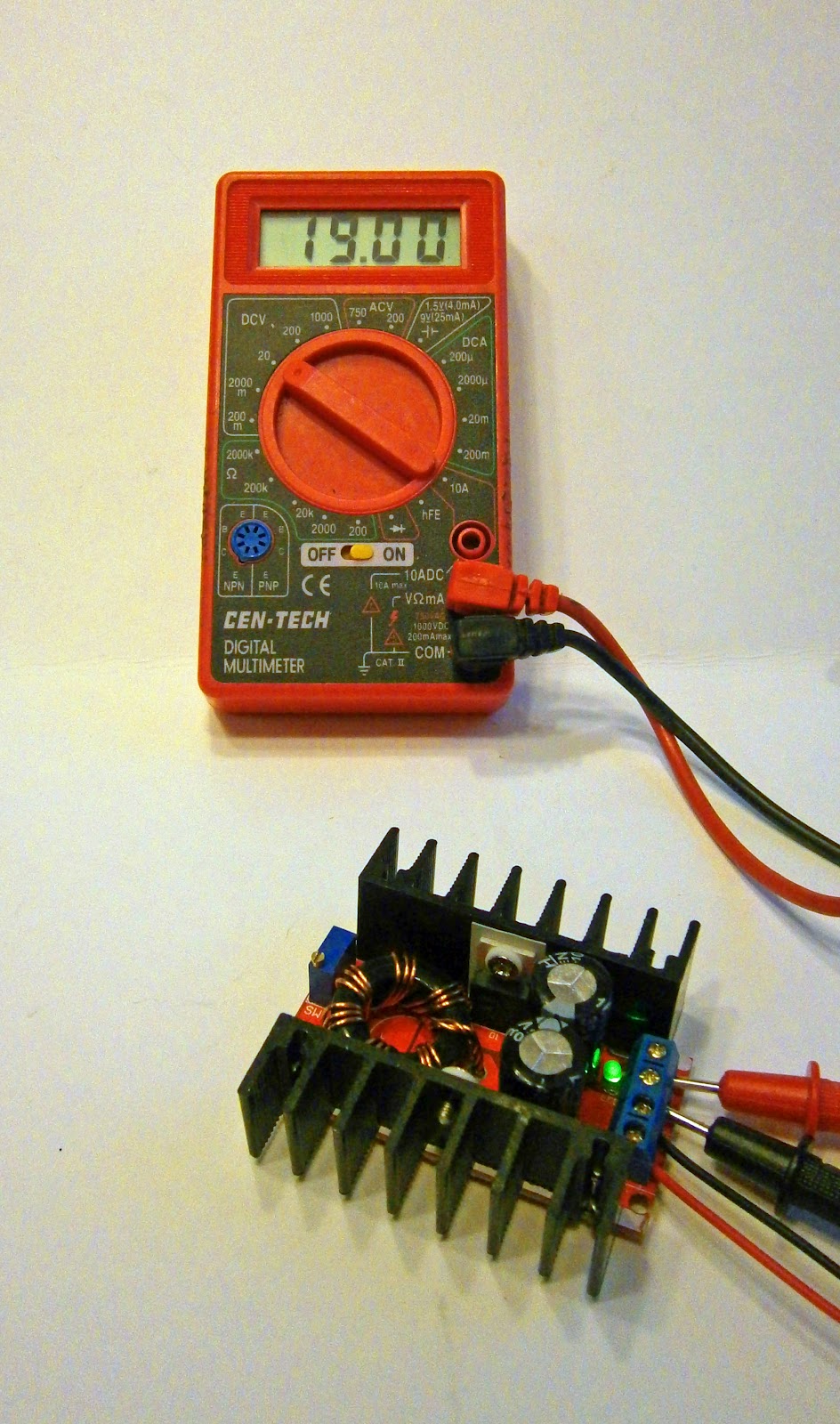
I proceeded to test the circuit. I connected 12VDC to the inputs and a voltmeter to the outputs. I adjusted the potentiometer (the blue component with the screw on top) on the board to get an output of 19V, as you can see in the next photo.


Notice that right behind the terminal strip there is an LED which is illuminated when the board is powered up.  19V is sufficient to run most DCC systems; besides if you keep the input voltage to your DCC system as low as practical, you'll get the maximum DCC current output, plus you'll minimize the generation of heat in this circuit. So far, so good.

Next I connected a power resistor (measured 20.2 ohms) to the output and put the meter in current mode to test for the output current. With an expected output of an amp at 19V, you cannot use an ordinary resistor for this, it will go up in smoke.


The power resistor is the device at the center. The 0.94 amps shown on the meter is the proper output for the voltage and the value of the resistor. After a few seconds of this output, the resistor became uncomfortable to handle, however the circuit board was still cool; very promising.

The next photo shows the trade-off for getting a higher voltage output from a lower voltage input.  The power supply providing the 12V input is supplying 1.62 amps to get the 0.94 amp at 19V out.


This will not generally be a problem as your PC power supply can likely provide more than enough amps at 12V to get a 5 amp output at the 16-22V required to run a DCC system.

Next I took two 10 ohm power resistors and connected them in parallel to produce an approx 5 ohm resistance (I measured this at 5.5 ohms but this cheap multimeter is known unreliable at measuring small resistance values).  This time I connected it to a PC power supply as the bench supply that I used in the first test would not supply enough current. As expected, the circuit output more current into this lower resistance; 3.6 amps as shown in the next photo.


At 19V/3.6 amps output the heatsinks on the circuit were warm and not excessively hot. I do not have any resistors of high wattage and low  resistance to test this circuit further.  However, I believe that an output of 19V/5 amps (95 watts) can be achieved.

Without further testing, here are some suggestions for finishing this circuit for use with a DCC system.  First and foremost you must fuse the output.  Even a momentary short circuit will fry the ICs that comprise this boost converter.  I'd use a fast-acting 6 amp glass fuse (GMA-6A) and matching fuse holder.  That may be hard to come by locally (although Home Depot does list these fuses on their website), so the fall back would be to use a 5 amp automotive blade fuse and fuse holder which you can find at your local auto parts store.

Use heavy wiring when wiring this circuit to your PC power supply and to your DCC system.  You'll be carrying heavy current out of this circuit and even heavier currents will be feeding into it (probably in excess of 12 amps).  14 gauge would be a minimum.  Be sure to heed my admonition in the article on converting PC power supplies to aggregate several distinct black (ground) and yellow (12V) wires from the power supply for the inputs to this circuit.

House this circuit in a metal project box; and a ventilated one would be much better as the circuit will produce heat during operation.

Adjust the circuit for a voltage a 2-3 volts above the minimal voltage needed to run your DCC system.  The output of this circuit may sag under load (however, it was a stable at 19V with the 3.6 amp load) and you want it to stay above the minimum for your DCC system.  Do not exceed the maximum input voltage for your DCC system.

Once connected to your DCC system, test that the circuit can supply sufficient output to allow the fast-acting DCC circuit breaker in your system to operate.  Put a dead short on the tracks and test that the DCC output goes to zero instantly.  If not, the circuit cannot handle the current surge and should not be used.

That's about it.  At some point in the future I will use this set-up to power a Lenz Compact DCC system for my bench.  At that point I'll write another blog post with the results.  If you get around to doing something first, let me know the results.


Roster Shot


Some time back, I wrote a post about an old school "box of sticks" boxcar kit that I had nearing completion after starting it more than 20 years previous (see Oldie But Goodie?). Well it's taken a couple of more years to finally get it done but, as you can see, it's on the layout, painted and operational. 

There was a great sense of satisfaction in finally finishing this project.  This is in spite of the fact that I could have purchased an Atlas O Trainman model of essentially the same prototype for about $42, taken it out of the box, put it on the rails and have been done with it.  Arguably my model is inferior to the Trainman RTR.  My model is missing a few details (most notably some of the grabs and the brake staff and wheel, which I will remedy); however, my brake rigging (borrowed from an Intermountain kit) is freestanding rather than the cast on blobs of the Trainman.

Where a kit like this really shines is in confidence building.  It probably took me as long or longer to build this kit as it would have taken to scratch build it.  However, faced with the terra incognita of scratch building this prototype, I might never have started.  The kit gave me a road map, however sketchy, for turning a box of sticks into a boxcar; and the confidence that someone, somewhere at some time thought that this could be done, therefore I should be able to do it as well.

It's a shame that these types of kits are no longer available as I have found that they can be great builders of proficiency.  But wooden kits have long been relegated to ancient history and the more recent cast-resin kits are on their way out as the makers of resin kits retire. 

Speaking of cast resin, I have a bunch of these kits and one is under construction and is next up for completion after I finish a Red Caboose tank car kit.  Stay tuned.

Monday, May 7, 2012

On Grades and Helpers

For starters, here's a quick video that I shot entitled "The Cheat River Grade Helper":


After shooting this video, I realized that I should do something about the bare backdrop on the Cheat River Grade. I cannot make a photo backdrop right now, but maybe I can at least paint the backdrop a sky blue.

 In my previous post, I remarked on the necessity for using helpers (or more head-end power) on the Cheat River Grade. This grade is 2% and nearly matches the prototype. In building my model railroad I have used Charles Roberts' book: "West End" as my "bible". My experience with needing helpers on the grade caused me to review the section in Roberts' book on equipment. Roberts compiled statistics on how many cars the prototype could pull up the grades. He used an interesting metric, number of cars puled per powered axle. Using this as a metric eliminates the differences in wheel diameter, steam vs. diesel, etc. What he found was that over the period of time from 1850 to 1991, the B&O could haul between 2.1 and 2.4 cars per powered axle up the grades. That is essentially the same result that I have obtained after testing with several model steam and diesel locomotives; between 2 and 2.5 cars per powered axle (and the latter number with a lot of wheel slip).

I believe that John Armstrong observed in one of his books on layout design that given needle-point axles model locomotives will pull more on the grades and less on the flats than prototype locomotives. He further observed that to create a helper grade that would seriously challenge model locos, 3% was about right.  I would certainly never dispute John Armstrong, but in my particular case the grades and, especially, for the combination of curves and grades, 2% seems to be about right.

It will help that most of the hoppers going up the Cheat River Grade will be empty (unlike the video above, which was just for fun) and I can arrange that most of those will be plastic models.  But the loaded hoppers coming down the Cheat will have to go up Cranberry Grade, also 2%; and these hoppers will be loaded.

During the period 1949-1952, the B&O used A-B-B-A sets of F7 diesels as pushers to help trains headed by, typically, a 2-8-8-4 articulated up both of these grades.  Assorted 2-8-8-0s and Q4 2-8-2s (as seen in the video above) were also used as pushers.  I intended to use A-A sets of diesels and Q4s as pushers.  The eight powered axles on the diesel pushers would be about 16 cars capacity, that should be OK.  The four powered axles on the Q4 would only be 8 car capacity - that might not be enough.  Matching the pusher to the train length could make the operating game more interesting.