M&K Junction Railroad

M&K Junction Railroad
Another train of eastbound coal crosses the Cheat River

Monday, January 16, 2012

Using Specialty LEDs Part 1

The following is an unfinished chapter in an e-book that I am writing about practical electronics projects for model railroaders. Stay tuned for the complete chapter.

Previous installments include:

Fun with LEDs

Fun with LEDs II
Fun with LEDs III

This chapter builds on the ideas and demonstrations in the previous ones, so if you are not savvy with LEDs, you may want to read these first. If you are knowledgeable about LEDs, you may find those and this installment to be old news.


Using Specialty LEDs


(c) 2011-2012 T. Terrance

There are a number of specialty LEDs and LED strips that are available that can be useful for model railroads. There are LEDs that flash, flicker, display red/green/yellow in a single LED; as well as tiny 'surface mount' LEDs and LED lighting strips, both in many colors. This chapter will show you how to work with some of these LEDs and along the way you'll have enough knowledge to build the electronic guts of a Flashing Rear End Device (FRED), maybe a model campfire or two as well as light passenger cars.

Flashing LEDs

Flashing (blinking) LEDs are available from many sources: Miniatronics 12-130-03 and other numbers; All Electronics CAT# LED-4; Radio Shack 276-312; Mouser and Digikey have too many part numbers to list here. Use their on-line product selectors search for keywords 'flashing' or 'blinking'. Flashing LEDs are usually found in red, green, blue, yellow and white. When selecting a flashing LED look for the operating voltage (usually 3-3.8 VDC), the current requirements (in milliamps) and the brightness in millicandellas (mcd); although there is a workaround for a dim flashing LED as we will see.

Flashing LEDs have a built-in 'chip' that makes the LED flash. The next photo shows the chip inside of a translucent yellow flashing LED.


Using most flashing LEDs is simplicity itself. Simply hook the LED up to 3V DC, observing the proper polarity, and they begin flashing - no resistor is necessary if you run them on 3V. Here's a photo of three flashing LEDs in a simple test setup.


In the front is a flashing red LED from Lumex (Mouser part #696-SSL-LX5093BSRD, Lumex part #SSL-LX5093BSRD), next is a yellow flashing LED also from Lumex (Mouser part #696-SSL-LX5093BYD, Lumex part #SSL-LX5093BYD); both of these LEDs were salvaged from another of my projects and have had their leads cut short. The LED in the back is the aforementioned All Electronics flashing red LED. The LEDs are plugged into a 'solder less breadboard' which is a gizmo electronics geeks use to quickly make up test circuits without soldering. 3VDC is being brought in on the red and black wires to the rear. The photo caught the All-Electronics LED flashing while the others were off.
 
Here's a video of those LEDs in action, first with the room lights on and then, from a different angle, with lights off.


One thing that you will notice is how feeble the yellow LED is compared to the red. This is normal, red is usually brighter than the other colors; pay attention to this if you are ordering colors other than red from Mouser or Digikey where you may have many flashing LEDs to choose from.

Most flashing LEDs flash at a rate of 1 1/2 to 3 times a second. This may be too fast for some model railroad applications. Can they be slowed down? Yes they can. By dropping the voltage these LEDs will flash at a lower rate. The flash rate will go down as the voltage goes down below the nominal 3 VDC. The rate at which the flash declines is not linear, that is in the first volt below 3 VDC, the flash rate slows down quickly. The flashing will stop altogether at about 1.5 VDC. Here are the flashing red LEDs from the first video clip (All Electronic (to the rear) and Lumex) flashing at 3 V, then 2 V (11 sec. into the video) and finally at 1.7 V (19 sec. to the end).


You'll notice that as the voltage drops, so does the brightness of the LED. Without going into theory, this is to be expected. But can this be fixed? Yes, in two ways. You can start with a brighter LED; then as the voltage drops the brightness will drop too, but it may still be bright enough to be usable. The problem with this is that the selection of blinking LEDs is rather limited and you may not find one bright enough for your needs.

The other way is to put another, brighter LED in series with the flashing LED. Another LED in series with the blinking LED will flash in sync with the flasher LED. (See
Fun with LEDs
for an explanation and demonstration of LED series circuits). The selection of super bright LEDs is large and growing, so this method allows you to flash a super bright LED.

In the next video clip the dim flashing yellow LED from Lumex is wired in series with a high-brightness yellow LED with a clear lens. You see the LEDs flashing in sync with the room lights up and then in the dark.


If you remember from the previous installment, LEDs in series require a higher voltage than a single LED. The flasher LED requires about 3 VDC, a regular yellow LED requires about 2 V therefore we would expect that the combination would require 5 VDC to make it work; and indeed the demonstration that you saw above was running on 5 volts. Neither LED would light nor flash below 3.8 VDC. If you need to flash more than one additional LED, then the voltage required to run the circuit will increase about 2 V for each additional LED.

If you reduce the voltage to the series-wired LED+flasher the combination will flash more slowly; as the following video demonstrates.


In this video the red Lumex flashing LED is wired in series with a super bright red-orange, clear lens LED. The combination is running on 3.6 VDC. Compare the flashing rate with the video immediately above to see the effect of reduced voltage.

By the way, in the example above I've paired yellow flashers with yellow LEDs and red flashing LEDs with other red LEDs. However, the color of the flasher and the color of the LED that you put in series with it is totally independent, you can pair any combination of colors. This allows you to flash LED colors that do not come as flashing LEDs. The LEDs need not be of the same size either; the flashers that I have used are all 5 mm size (other sizes are available) but the series LED can be any other size, including surface mount LEDs. This allows you to flash surface mount LEDs which are not manufactured as flashers.

Are there other ways to flash an LED? Yes there are, but for simplicity the self flashing LED is hard to beat. When I write the chapters on building electronic kits and 'rolling your own' circuits, LED flashing circuits will figure prominently. At that time I'll talk about alternate flashers as are needed for grade crossings.

At this point you have enough information to make stationary flashers for most any scenery purpose, e.g. towers, advertising signs, bumpers, police and fire apparatus, etc. However, your power source needs to be low voltage DC. The easiest way to get pure DC is, of course, to use a battery. A pair of 'D' size batteries (3V) will power one of these flashers continuously for a year (I've actually done this experiment). If all of your LEDs are self-flashing, then wire them in parallel to 3V. If you have series strings of flashers and regular LED's, add more batteries to increase the voltage, as mentioned above. Hide the battery holder beneath the scenery and add an on/off switch and it will be a long time between battery replacement.

If you want to run your flashing LEDs from an rectified AC source, that includes any DC output of a power pack, 'wall wart' DC transformers, or a transformer/rectifier combination, you must follow some additional steps. First, you'll need to determine the polarity of the output terminals with a multi-meter as they are rarely marked. Next, the voltage is likely to be around 12V, especially using the fixed DC output from a power pack. Since the output of most power packs (as well as DCC and 'wall warts') is higher than 3-5 VDC you'll need a resistor in series with the LED(s) to drop the voltage a bit. Start with 1500 ohms and adjust up or down based on the brightness and flashing rate that you get. Most flashing LEDs will work fine with just a resistor to limit the current/voltage. Try this arrangement first and if it works, yuu can skip down to beyond the next couple of pictures. However, if your LED does not flash it may be that it does not like unfiltered DC. If your LED doesn't flash or is on constantly, you'll need to add a filter capacitor to the power supply output.

There are many different type of capacitors, (BTW, "cap" is used as shorthand for capacitor) the ones typically used for filtering are called 'electrolytic' capacitors. The key feature of electrolytic capacitors, for our purposes, are that they are polarized, that is they have a positive and a negative terminal; and must be hooked up with the proper polarity.

Capacitors are characterized by two values: their capacity (i.e. how much charge they can hold) and their voltage. Capacity is measured in microfarads (abbreviated uF). To filter a power supply for a reasonable current draw between 1/2 and 1 amp you'll need at capacitor between approximately 5,000 and 10,000 uF. As for voltage, a 35V or 50V cap should suffice. If you have a capacitor with higher capacity or higher voltage, it's OK to use.

Radial capacitors (that is, capacitors with both leads coming out of the same end of the device) can be obtained from: All Electronics (4700 uF, 65V, $1.65); MCM Electronics #31-5120(6800 uF, 35V, $5.14); Mouser #647-UVZ1V682MRD (6800 uF, 35V, $2.66); Mouser #647-UVZ1V103MRD (10,000 uF, 35V, $3.27); among many, many other sources. These types of capacitors are commodity items; so select one based on availability and price.


2200 uF, 35V Radial Electrolytic Capacitor

Filtering the power supply is straightforward. Attach the positive terminal of the cap to the positive output and the negative terminal to the negative output. That's it. Here's a video of a 1980's vintage MRC Tech II 2500 power pack with a filter capacitor on the fixed DC outputs running a flashing LED.


For this demonstration I've simply inserted the capacitor's leads under the fixed DC output terminals, observing the proper polarity. The resistor next to the flashing LED is necessary to reduce the approximately 12V output of the MRC 2500 to a value safe for the LED. This resistor is 1500 ohms, the value will be more to slow down the flashing rate. The value of the resistor will be less if you want to run a series-connected string of LEDs+flashers.

Now that we've discussed stationary flashing LEDs, what do you have to do to put a flashing LED into a car or locomotive? The simplest thing to do would be to battery power your mobile flashing LED. If you have space for a couple of 'AAA' batteries for 3 VDC (or four AAA batteries producing 6VDC for a series circuit) and an on-off switch you will not have to worry about reversing polarity on the rails, DCC square waves on the rails, over voltage or anything else. A battery-powered flasher will also flash when track power is off. AAA batteries will last a long time in this application.

If you must power the flashers from the rails then a rectifier and resistor will be necessary, as was demonstrated in the first installments (see Fun with LEDs II ). One additional component will be required to make the circuit function correctly; that component is a Zener Diode.

In a mobile application, the flashing LED may see as much as 18V from the rails and the chip inside of the LED needs to be protected form that high of a voltage. In addition, the use of a zener diode will allow you to have some control over the flashing rate by adjusting the voltage that the blinking LED sees.

A Zener diode is a special kind of diode which allows current to flow in the forward direction like a regular diode, but will also permit it to flow in the reverse direction when the voltage is above a certain voltage known as the breakdown voltage. When connected "backwards" (that is with its cathode connected to the positive voltage and its anode connected to the negative voltage) the zener will not conduct until it's breakdown voltage is reached. At or above the breakdown voltage the zener conducts and this trait can be used to limit the voltage that the flashing LED will see.

To accomplish this we put a zener diode across the + and the - after the resistor, but before the LED(s). The diagram below illustrates the set-up (click on the picture for a larger view).
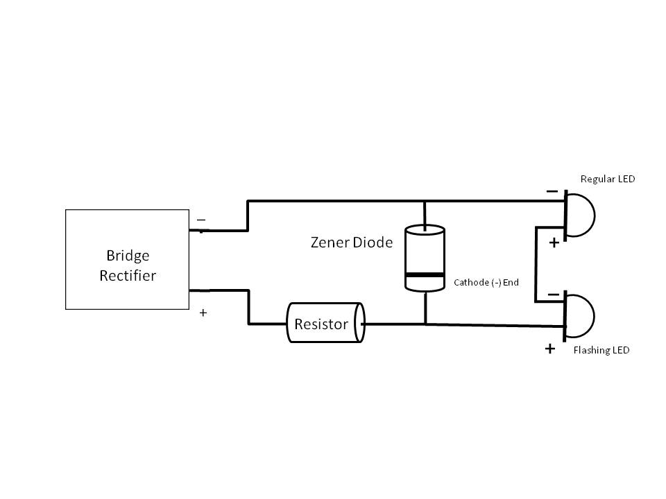


I've drawn this with two LEDs, if you want just one, just ignore the second. The cathode (negative end) of the zener is marked with a black band. It needs to be hooked up to the POSITIVE side of the circuit. The circuit works in this way: As the voltage from the track starts to rise, the LED(s) will begin to flash. When the voltage exceeds the zener's voltage, it will begin to conduct allowing current to flow from + to -. Once it starts to conduct, the voltage in the circuit will not rise beyond the zener's voltage. And, by the way, the flashing will be at a constant rate after the zener conducts and limits the circuit voltage.

It is imperative that the zener's connection point occur after the resistor. The resistor in this circuit limits the current through both the LED(s) and the zener. If the zener is placed before the resistor, when the zener conducts too much current will flow and the zener will burn out.

Zener diodes are characterized by their breakdown voltage and their ability to handle current. For any reasonable string of LEDs used on a car or locomotive, a 1/2 watt (500 milliwatt) zener should be sufficient. 1, 2 and 3 watt sizes are also available, although they can get physically large. Use the table below to select the proper zener voltage.


Flasher alone
Flasher + 1 LED
Flasher + 2 LEDs
Normal flash rate
3V
5V
7V
Slow flash rate
1.8
3.8
5V


These zener values are suggestions, your LED or combination of LEDs may require a higher or lower voltage zener. Zener diodes usually do not come in even integer voltages, they will be something like 3.1V or 5.2V. Choose the value that you can find nearest to the ones in the table, getting the exact value is not necessary. Radio Shack has only 2 zeners (5V & 12V). NTE Electronics also has individually packaged zener diodes which can be found in stores dealing with electronic components. Mouser and DigiKey have a wide selection of zeners.

Here, I've built a mobile version of the flasher with a zener diode. This photo shows the rectifier, resistor and zener:


The cathode end of a 5.1 V zener is connected to the positive side of the circuit beyond a 1500 ohm resistor. the white wire is carrying the positive current to the remotely mounted LEDs and the blue wire is carrying the negative current.

Two series-connected LEDs are at the ends of those wires. One is the yellow flashing LED (Lumex) and the other is a 1.6 mm red, clear lens LED like the one in the next photo:


This tiny LED is small enough to be a F.R.E.D. in just about any scale including 'N'. Here's a video of both LEDs running on DCC track power (square-wave AC).


The yellow LED barely flashes while the tiny red LED shines brightly. This is just as well as the yellow flasher should be hidden with the rest of the circuitry.

If your flashing LED does not like the unfiltered DC that the rectifier outputs, then a small electrolytic capacitor will have to be added to the set-up.

As the final demonstration in this installment, here is a variation on the flashing LED, the flickering LED. These LEDs are found in LED "Tea Lights"; I bought mine at a dollar store 3/$1.


However, if you cannot find these tea lights near you, Electronic Goldmine has the bare LEDs: Flickering LED.

Here's a video of a flickering LED extracted from a dollar store tea light. First just the LED with its silicone-rubber candle top, then the flickering LED in series with a regular yellow LED.


Extracting the LED from the tea light is straightforward. Everything that applies to flashing LEDs applies equally to the flickering LED; voltage levels, series circuits, etc. A few of these hooked up to yellow, orange and red LEDs should make a convincing campfire. Especially if the LEDs were tiny surface mounted LEDs; but surface-mount LEDs are a story for another installment.

The next installment will deal with bi-color LEDs.

Monday, January 9, 2012

That Was The Year That Was

2011 was a pretty good year; in spite of getting off to an inopportune start. The year began with my first Open House for the Baltimore/Washington O Scale group on Jan. 8. A flurry of activity during the Christmas week just past had brought the layout to just about 70% of the way around the walls of the basement; not much to show for 3 1/2 years of construction.

Jan. 8, 2011 saw a light snow on the ground here in Virginia which deterred several people from attending (snow in any amount usually shuts things down here in VA). To make matters worse, a careless driver went whipping around a turn in the slick snow, couldn't hold the turn, crossed the line and wiped out my wife's car as she was on the way to pick up the 6' sub for our lunch! 2011 was off on a bad foot.

Despite all of that 11 people attended the Open House and I believe that a good time was had by all.

About mid-year the previous year, I had an idea for staging tracks and a reverted loop that I had not included in the original plans; but, if they were to be built at all, it had to be done before the main line progressed too much further. Building what I came to call hidden staging took a lot longer both before and after the the open house than I had anticipated. The first trains were not ready to run in hidden staging until the latter part of July 2011 (Aargh!) see First Train Runs in Hidden Staging.

From there on out, it was preparation for my second open house which I had committed to for Sept. 10. In the couple of weeks leading up to the second Open House I put in the Tray Run Viaduct trackage and almost all of the rest of the Cheat River Grade. (see Work On The Mainline Resumes and More Progress and T Minus 5 and Counting and D-Day). Nothing like a deadline to concentrate your efforts.

After the open House, the Cheat River Grade backdrop went up; see A Backdrop for the Cheat River Grade. Finally, the year closed out with construction beginning on the helix; see Construction of the Helix Begins.

Between all of this I produced three instructional videos (Fast Tracks Tips and Techniques, Install a DCC Decoder in a Brass Steamer, Photo Backdrops Made Easy) several smaller videos and several instructional postings; had my first published article and appeared on many episodes of Model Rail Radio. And, oh yeah, my day job was pretty demanding as well.

Although I would liked to have done more, 2011 has been my most productive year. Looking forward to 2012, I want to complete the helix and at least one track on it by my next Open House, Apr. 21. After that, I hope to have the golden spike ceremony for completion of the main line by the end of the year.

Wish me luck.

Saturday, December 31, 2011

Construction of the Helix Begins

My main task for the Christmas-New Year's week was to begin construction of the helix at the center of my layout (see Track Plan). Completion of the helix will allow for continuous operation. The two-turn, double-tracked helix also serves as serial staging and will hold (2) 25 car trains in each direction. I've set myself the task of completing the helix and at least one track on it by April 2012.

I had designed and ordered a template to cut the sectors of the subroadbed and lay out the center lines of the two tracks (see Track Templates), but the benchwork to support the subroadbed had not yet been designed. I used TurboCad 14 Delux to design the benchwork for the helix.

Helix benchwork2

The octagonal benchwork is made up of 8 trapezoids 44.25 x 58.25 x 18.75 on the short side. The two concentric circles indicate the subroadbed. Radii on the helix are 66.5 inches and 62 inches. The benchwork is 141 inches across - this is some helix!

Here I'm using the helix template to mark out the subroadbed prior to cutting.


I do my cutting outside, wherever possible. Here are 9 sectors of subroadbed, the yield of one sheet of 3/4 inch plywood.


The photo above shows the decks of the first four sections of the helix benchwork completed. The following photo shows the first three sections of benchwork assembled as a test. These sections are not in their final position.


The benchwork is 54 inches to the top. My current thinking is that only every other section will have legs; alternate sections will be suspended between the sections with legs. Squaring-up and leveling the benchwork may be difficult with this arrangement; if so, I will have to attach legs to each section so they can be leveled separately.

Corporate Logos for Sign Making

While searching for corporate and organizational logos to use in making signs for my layout I came across these sites:

http://www.seeklogo.com/

http://www.brandsoftheworld.com/

http://www.firestonetire.com/Media/LogosTirePhotos.aspx

http://www.bridgestonetire.com/Media/LogosTirePhotos.aspx

On the first two sites there are thousands of logos from all over the world each, apparently, drawn and contributed by volunteers; so they’re all free for private use. There are even some railroad logos in the group. I'll intersperse some examples of logos with the text of this post.


Some of the logos are 'alpha masked', which means that you can use them as transparent overlays over other graphics, like placing them directly on a brick texture to make a painted-on wall sign.

The good news is that these are all in vector graphic formats: Encapsulated Postscript (.eps), Adobe Illustrator (.ai), Adobe Postscript (.ps) or Corel Draw (.cdr). Because these are vectors and not bitmaps (pictures) they can be scaled to whatever size you want and they will still look good. The bad news is that most of us do not have the high-end, vector graphics programs like Adobe Illustrator or Corel Draw and therefore we cannot readily read or manipulate these files.

That does not mean that you cannot use these files, but you will have to work at it. My copy of Microsoft Word from Microsoft Office Enterprise Professional 2007 will open all of the Encapsulated Postscript (EPS) files. To do this click on the .eps file, copy it, place the cursor where you want the logo inserted into your Word document and then select paste. The logo will be inserted into Word. You can then click on the logo, grab any of the ‘handles’ that appear and resize the picture. Grabbing one of the corner handles and moving diagonally in or out will allow you to resize without changing the proportions of the logo. I don’t know if older versions of Word will open these files.

The version of Microsoft Power Point, also from Microsoft Office Enterprise Professional 2007, will open the EPS files using the exact same procedure. This is the better option as Power Point has better drawing tools to use with the logo you just imported.

Recent versions of the Adobe graphics tools (Adobe Photoshop, Photoshop Elements) will open the .eps files. If you don't have Photoshop, trial versions of this software good for 14 days can be downloaded from Adobe. Before you try this, search the websites above and download all of the logos you are likely to want as you will be working against a time limitation. Once you have Adobe installed, open all of the logos, scale them to the sizes that you will need and then save each as .jpg or some other format that many applications can open.

Once you can read and manipulate .eps files, then next thing to do is to try to convert the Adobe Illustrator, Adobe Postscript and Corel Draw files to EPS.

Download a trial version of Corel Graphics Suite from here:

http://www.corel.com/servlet/Satellite/us/en/Product/1208530085783#tabview=tab7

The trial version is good for only 15 days, so install it only when you have the time to do all of the conversions. Using Corel Draw you can drag n’ drop the .ai files into Corel. If you are asked how to import text, click the radio button to import text as curves doing so will preserve scalability of the drawing. To write the file as an EPS file, choose ‘export’ from the file menu; in the next dialog box give it a file name and select EPS as the file type then click ‘export’; in the next dialog box set the resolution to 300 dpi or higher, and select to export text as curves; the final OK writes the file.

Of course, while you have the trial copy of Corel, resize and print all of the logos that you think that you will need.

Corel will not be able to import all of the .ai (Adobe Illustrator) files; but those that it does open seem to export to EPS correctly. Setting the resolution to 300 dpi makes the resultant EPS file smoother than it would be otherwise. You might want to consider redrawing all of your EPS files at 300 dpi in this manner. Obviously, Corel can read and convert its native .cdr files to .eps using the same procedure. The Corel Suite has an application called Photo Paint, that can do a similar job, but it does not preserve the scalability as well as Corel Draw does.

Friday, December 30, 2011

Industrial Shelf Layout

Here's an industrial shelf layout that I designed for Model Rail Radio. It's tightly packed with close clearances but. if done with typical brick, high rise (5-6 story) urban buildings, moderately weathered and sprinkled with detritus, it should be a scenic success. It's designed for 2-rail O Scale (or P48)but may be do-able in 3-rail sectional track. Click on the drawing to enlarge. Design notes follow the drawing.


Urban Jungle

'O' Standard Gauge or P48 Shelf Layout

General Notes:

  • Built from (5) 19" x 48" ppanels cut form a 4'x8' sheet of plywood and arranged into a 144" x 115" x 19" 'L'
  • Designed for 40' cars (the additional 2 1/2 inches of the 50' cars was a capacity killer)
  • Designed for small locomotives
  • GE 44, 45 and 70 Ton
  • NW-2, SW-8/9, SW1200/1500
  • Alco S1/S2
  • 0-4-0 and 0-6-0 Steam, saddle tank would be perfect; however, there is no provision for turning the locomotive end-for-end
  • (2) 33"x9" traversers (9 car capacity each); tracks on 3 1/8 inch centers
  • 35+ car capacity (17 industrial spots, 18 on the traversers)
  • Curves, what few there are, are 26" minimum radius - tight, but with short (40') equipment it will look OK, No equipment needs to couple/uncouple on curves, nor be parked on curves.
  • All turnouts (except one) are #4, drawn to NMRA minimum dimensions. Can substitute old (1970's) Atlas/Roco O turnouts (check loco compatibility) and free up some space.
  • One 30/26 radius custom-built turnout. This one will have a LONG frog, probably #12 or better.
  • Designed to slow down operation:
  • Extensive use of switchback setouts will require moving cars already spotted to position new cars.
  • Two car capacity on the run-around limits the number of cars that can be pushed/pulled into position in a single move.
  • Estimate 2-3 hours to move and spot all cars on the layout.
  • All buildings are 5-6 storied high and the layout is high enough that the tops of the buildings are at or above eye level. This creates the feeling of an urban canyon and hides the building-to-backdrop transition.

Specific Notes (keyed to the letters on the layout)

  • (A) Large industry - Brewery, urban bakery, freight storage warehouse, paper mill, etc. chosen for car variety. Hides one of the traversers. RHS wall removable to fiddle cars onto and off of the traverser.
  • (B) Freight house/meat packing/cold storage/produce distributor. Semi-flat against wall, two track awning over house tracks or tracks in open-air arcade under building. Second loading track served by 'bridge plates' between cars on the nearesst track and cars on the outer track; complicates loads/empties spotting.
  • (C) Irregular shaped building built on 'air rights' (stilts) over the tracks. often found in crowded urban areas; adds scenic interest. One spot loading dock underneath. Unfortunately, the building sits atop one turnout; prototypical, but could be a maintenance headache.
  • (D) Semi-flat buildings against wall. Set at irregular angles helps disguise the rectilinear arrangement of the track on the shelf. Tracks enter one structure, loading doors in the walls of the others.
  • (E) Open-air industry; iron works, scrap yard, sand& gravel, fuel (oil or coal), concrete, etc.
  • (F) High retaining wall with portal. This is the layout's 'beyond the basement' connection and portal to the other traverser.
  • (G) large building built on a bluff above; hides the traverser and continues the urban theme. The end is left open to fiddle cars onto and off of the traverser.
  • (H) Run-around, two car capacity; limits the size of set-outs, slows down operation.
  • (I) Loco pocket or team track.

Final Thoughts:

  • All clearances are tight and a lot of 'No Clearance' and 'No Clearance for Man Riding Car' will be prototypical.
  • I've done a preliminary fit check and a few adjustments will have to be made during construction:
  • The two tracks leading into industry A need to be shifted slightly towards the front of the layout to assure clearance with the tracks at industry B.
  • Check and adjust clearances around industry C where the track comes near the wall.
  • If desired, the layout can be modeled as a harbor scene, with the harbor located in the aisle. the aisle side of the layoout is them modeled as bulkhead; industry A and E then have water-borne service as well as rail serevice. Tracks leading into industry A can double as pier tracks for rail/water transfer with an impressive traveling overhead crane.
  • Could be done as traction; the wire entering the buildings would make for some interesting wire work.
  • This layout could probably handle a collection of 100+ cars so that cars do not repeat trips to any given industry too often.

Sunday, December 25, 2011

Photo Backdrops Made Easy

A few weeks ago, I appeared on the Model Railcast Show speaking about Photo Backdrops. For me, photo backdrops are the best alternative as I have little or no artistic ability for painting a backdrop. While the process of creating a photo backdrop sounds involved, once you have all of the tools together and pictures together, you can turn out a backdrop in 15 minutes - literally.

Because my narrative on Model Railcast was not complete, I made the following video explaining and illustrating the process. After viewing the video, be sure to read my notes and outline below it.

I've included two versions of the video. If you can use the HD/widescreen version you will be able to view the screen shots embedded in the video better. Try turning off HD in the play bar if your computer is running slow. For slow computers and slow internet connections, I've created a standard definition version. Be sure to use the full screen button in the play bar in either case.


High Definition/Widescreen


Standard Definition


Photo Backdrops Outline

(c) 2011 T. Terrance

1) What you’ll need:
  • Computer – A reasonably recent computer, dual core preferred, but not required.
  • Software – Open source, commercial and trial versions
  • Camera – Digital preferred, although film converted to digital or scanned photographs will suffice.
  • OR access to on-line textures (e.g. CG Textures, etc.) for the subject material

2) Collecting the ‘stuff’

  • Computer 3 GHz or better single core, or multi-core
  • Software

i) Open Source – GIMP, Inkscape

ii) Commercial – s/w that came with your camera; Photoshop Elements – sometimes a free copy is included with your printer; Photoshop, Corel Photo Pro, etc.

iii) Older versions of commercial software are sometimes available at a bargain price.

iv) Get on mailing list of Corel, Adobe, etc. for outgoing versions at a discount. I just bought Corel Photo Pro 3 for $9.95 with free shipping directly from Corel.

v) Trial versions – you can do everything with 14-30 trial versions of the best commercial software, you just have to get all of your work ready and dedicate the time to finish before the trial runs out. Use Adobe and Corel tools trial versions serially. Install on multiple computers.

  • Camera- you don’t need a Gigapixel digital camera. You’ll be combining several photos into one thereby increasing the number of pixels. In addition, you want the backdrop somewhat soft, so it doesn’t attract the eye and detract from the trains. 7 MP is good enough.
  • No camera necessary to use sky and scenic textures from GC Textures.

3) 5 Steps to a photo backdrop

  • Take photos (or obtain them on line)
  • Stitch together
  • Compose; adjust color, brightness, contrast, etc.; remove out-of-scale elements; add details
  • Resize
  • Print

4) Taking photos.

  • Seek out vistas with a large expanse of scenery and sky. Alternately large industrial areas.
  • 10 am – 2 pm flat light. Sun at your back, if possible.
  • Avoid wide-angle setting if possible
  • Use panorama or scene mode if available on your camera.
  • Use a tripod, if possible, but hand-hold is OK. Pan level left to right.
  • Overlap each photo by 20%
  • Bracket exposures – it’s only electrons

5) Stitch photos together

  • Never work on your original files
  • Use the software that came with your camera or something like Photoshop Elements (tutorials on line)
  • Set-up the stitch mode. Likely to be pivot rather than shift.
  • Work in raw or TIFF if your camera offers it and your computer can handle it.
  • Consider stitching only 3-5 photos at once. The 20-30 MB file that results will grow awfully large after resizing.
  • Save the stitched file and a copy, do subsequent work on the copy.

6) Compose

  • Trim. Adjust skew, perspective.
  • Save intermediate versions.
  • Adjust color, temperature, brightness, contrast, sharpness. One-step auto-fix, followed by individual adjustments. Remember you have an undo button.
  • Save intermediate versions.
  • Most advanced photo suites have a tool to remove items from the scene, these may, or may not work. Against a backdrop of trees and/or wooded hills, the stamp tool can erase many ills.
  • Save intermediate versions.
  • Add back trees, buildings other detail either photographed or obtained on-line. Scale to fit before inserting.
  • Save intermediate versions.

i

7) Resize.

  • Resize only after all other adjustments to your panoramic phot have been made.
  • In your photo software, create a canvas at the size of you final print and with the native resolution of your printer (300-600 pixel/inch). Don’t go overboard on the pixel resolution, bigger is not necessarily better.
  • Drop you panoramic shot onto the canvas; move to upper left corner.
  • Use the resize/scaling tool. Lock the picture proportions. Expand in steps 10% at each step. Perfect Resize 7.
  • In the final stages, it will take you computer a LONG time to complete each resizing, be patient. Do it during lunch, overnight, etc. At some point the process may fail on your computer/software combination. Change software, borrow someone’s computer. USB drives are handy for file transfer.
  • A soft image after enlarging is OK, but it should not be not blocky.

8) Print

  • Work, universities often have large format printers.
  • Staples
  • Wal-Mart Photo dept. send-out (20x30, 6 & 8 foot banners)
  • On-line services, (e.g perfectposter.com)
  • Desktop printers to 13x19 and larger by using tiling
  • If your backdrop exceeds the capabilities of the printer that you have access to, then printing the backdrop in ‘tiles’ with or without overlap is possible.
  • Plain paper/ink is OK

Friday, December 23, 2011

LEDs for Layout Lighting?

A basement-filling layout can consume a lot of electricity to light properly. I currently use florescent lighting to illuminate my layout, but even florescents draw a bit of current when they are all on. LED lighting is the up and coming technology but, putting cost aside, are they suitable for layout lighting?

I've been collecting samples of LED bulbs and testing them on my layout and here are some results.

I've been testing 1+ watt LEDs and these do generate some heat and get hot; so hot in fact that the bulbs have built-in heat sinks. Because of how they are constructed, LEDs are good for spotlights, but getting the light to spread is difficult.

Here are some examples:

Here is a car on my layout with the layout lights off, but the room lights turned on. In this picture, the car is illuminated from 30 inches away by a LED bulb containing (4) 1 watt LEDs:

3x2

This is what that bulb looks like:

4x1

You can see the four 1 watt LEDs. Notice that the light is intense, but limited to an area slightly larger than the car itself.

Next is the same car, same place and same camera position illuminated with a single 3 watt LED spotlight:

3 watt

Here's what that bulb looks like:

1x3

This is not exactly a bulb, but a self-contained spotlight. 110V has to be supplied to the two wires, which is easily done with a electrical cord. Electronics in the base converts the 110V to use by the LED. Again the light is bright, but confined.

Here is the car illuminated by a 4 watt LED bulb that looks like a bulb.

4 Watt bulb

Here's what that bulb looks like:

Bulb

Before you say "Eureka! You've found it"; you need to see what ambient light is like. Here's ambient:

ambient

As you can see by comparing with the photo above, this bulb barely illuminates above ambient. It would only be good for mood lighting.

Since the high-powered LED lamps were not acceptable, I decided to try something else. There are bulbs made up of a number of surface mounted device (SMD) LEDs. The one that I chose to try has 60 SMD LEDs on it. Each one of the SMD LEDs contains 3 chips emitting light for a total of 180 LED emitters; color temperature is 6500 K. The bulb looks like this:


Unfortunately this bulb did not work out any better than the others. I could not get a good picture of the light output because the bulb seems to fool the sensor in my camera and the pictures have an strong overall blue tint. That alone would disqualify this bulb for photography purposes. The visual appearance of the light was much like the bulb immediately above, somewhat above ambient illumination. This bulb was mounted into a fixture that had a reflector, so all of the light was directed towards the layout.

Finally here is the scene lighted by a standard 60 watt bulb in the same fixture as the LED bulbs:

60 Watt

The nice, even, soft, well distributed illumination is hard to beat.

This has been somewhat of an apples to oranges comparison inasmuch as two of the LED bulbs were spotlights. But as you can see from the last LED bulbs, diffusing the meager light from an LED results in a very feeble light indeed.