M&K Junction Railroad

M&K Junction Railroad
Another train of eastbound coal crosses the Cheat River

Friday, December 30, 2011

Industrial Shelf Layout

Here's an industrial shelf layout that I designed for Model Rail Radio. It's tightly packed with close clearances but. if done with typical brick, high rise (5-6 story) urban buildings, moderately weathered and sprinkled with detritus, it should be a scenic success. It's designed for 2-rail O Scale (or P48)but may be do-able in 3-rail sectional track. Click on the drawing to enlarge. Design notes follow the drawing.


Urban Jungle

'O' Standard Gauge or P48 Shelf Layout

General Notes:

  • Built from (5) 19" x 48" ppanels cut form a 4'x8' sheet of plywood and arranged into a 144" x 115" x 19" 'L'
  • Designed for 40' cars (the additional 2 1/2 inches of the 50' cars was a capacity killer)
  • Designed for small locomotives
  • GE 44, 45 and 70 Ton
  • NW-2, SW-8/9, SW1200/1500
  • Alco S1/S2
  • 0-4-0 and 0-6-0 Steam, saddle tank would be perfect; however, there is no provision for turning the locomotive end-for-end
  • (2) 33"x9" traversers (9 car capacity each); tracks on 3 1/8 inch centers
  • 35+ car capacity (17 industrial spots, 18 on the traversers)
  • Curves, what few there are, are 26" minimum radius - tight, but with short (40') equipment it will look OK, No equipment needs to couple/uncouple on curves, nor be parked on curves.
  • All turnouts (except one) are #4, drawn to NMRA minimum dimensions. Can substitute old (1970's) Atlas/Roco O turnouts (check loco compatibility) and free up some space.
  • One 30/26 radius custom-built turnout. This one will have a LONG frog, probably #12 or better.
  • Designed to slow down operation:
  • Extensive use of switchback setouts will require moving cars already spotted to position new cars.
  • Two car capacity on the run-around limits the number of cars that can be pushed/pulled into position in a single move.
  • Estimate 2-3 hours to move and spot all cars on the layout.
  • All buildings are 5-6 storied high and the layout is high enough that the tops of the buildings are at or above eye level. This creates the feeling of an urban canyon and hides the building-to-backdrop transition.

Specific Notes (keyed to the letters on the layout)

  • (A) Large industry - Brewery, urban bakery, freight storage warehouse, paper mill, etc. chosen for car variety. Hides one of the traversers. RHS wall removable to fiddle cars onto and off of the traverser.
  • (B) Freight house/meat packing/cold storage/produce distributor. Semi-flat against wall, two track awning over house tracks or tracks in open-air arcade under building. Second loading track served by 'bridge plates' between cars on the nearesst track and cars on the outer track; complicates loads/empties spotting.
  • (C) Irregular shaped building built on 'air rights' (stilts) over the tracks. often found in crowded urban areas; adds scenic interest. One spot loading dock underneath. Unfortunately, the building sits atop one turnout; prototypical, but could be a maintenance headache.
  • (D) Semi-flat buildings against wall. Set at irregular angles helps disguise the rectilinear arrangement of the track on the shelf. Tracks enter one structure, loading doors in the walls of the others.
  • (E) Open-air industry; iron works, scrap yard, sand& gravel, fuel (oil or coal), concrete, etc.
  • (F) High retaining wall with portal. This is the layout's 'beyond the basement' connection and portal to the other traverser.
  • (G) large building built on a bluff above; hides the traverser and continues the urban theme. The end is left open to fiddle cars onto and off of the traverser.
  • (H) Run-around, two car capacity; limits the size of set-outs, slows down operation.
  • (I) Loco pocket or team track.

Final Thoughts:

  • All clearances are tight and a lot of 'No Clearance' and 'No Clearance for Man Riding Car' will be prototypical.
  • I've done a preliminary fit check and a few adjustments will have to be made during construction:
  • The two tracks leading into industry A need to be shifted slightly towards the front of the layout to assure clearance with the tracks at industry B.
  • Check and adjust clearances around industry C where the track comes near the wall.
  • If desired, the layout can be modeled as a harbor scene, with the harbor located in the aisle. the aisle side of the layoout is them modeled as bulkhead; industry A and E then have water-borne service as well as rail serevice. Tracks leading into industry A can double as pier tracks for rail/water transfer with an impressive traveling overhead crane.
  • Could be done as traction; the wire entering the buildings would make for some interesting wire work.
  • This layout could probably handle a collection of 100+ cars so that cars do not repeat trips to any given industry too often.

Sunday, December 25, 2011

Photo Backdrops Made Easy

A few weeks ago, I appeared on the Model Railcast Show speaking about Photo Backdrops. For me, photo backdrops are the best alternative as I have little or no artistic ability for painting a backdrop. While the process of creating a photo backdrop sounds involved, once you have all of the tools together and pictures together, you can turn out a backdrop in 15 minutes - literally.

Because my narrative on Model Railcast was not complete, I made the following video explaining and illustrating the process. After viewing the video, be sure to read my notes and outline below it.

I've included two versions of the video. If you can use the HD/widescreen version you will be able to view the screen shots embedded in the video better. Try turning off HD in the play bar if your computer is running slow. For slow computers and slow internet connections, I've created a standard definition version. Be sure to use the full screen button in the play bar in either case.


High Definition/Widescreen


Standard Definition


Photo Backdrops Outline

(c) 2011 T. Terrance

1) What you’ll need:
  • Computer – A reasonably recent computer, dual core preferred, but not required.
  • Software – Open source, commercial and trial versions
  • Camera – Digital preferred, although film converted to digital or scanned photographs will suffice.
  • OR access to on-line textures (e.g. CG Textures, etc.) for the subject material

2) Collecting the ‘stuff’

  • Computer 3 GHz or better single core, or multi-core
  • Software

i) Open Source – GIMP, Inkscape

ii) Commercial – s/w that came with your camera; Photoshop Elements – sometimes a free copy is included with your printer; Photoshop, Corel Photo Pro, etc.

iii) Older versions of commercial software are sometimes available at a bargain price.

iv) Get on mailing list of Corel, Adobe, etc. for outgoing versions at a discount. I just bought Corel Photo Pro 3 for $9.95 with free shipping directly from Corel.

v) Trial versions – you can do everything with 14-30 trial versions of the best commercial software, you just have to get all of your work ready and dedicate the time to finish before the trial runs out. Use Adobe and Corel tools trial versions serially. Install on multiple computers.

  • Camera- you don’t need a Gigapixel digital camera. You’ll be combining several photos into one thereby increasing the number of pixels. In addition, you want the backdrop somewhat soft, so it doesn’t attract the eye and detract from the trains. 7 MP is good enough.
  • No camera necessary to use sky and scenic textures from GC Textures.

3) 5 Steps to a photo backdrop

  • Take photos (or obtain them on line)
  • Stitch together
  • Compose; adjust color, brightness, contrast, etc.; remove out-of-scale elements; add details
  • Resize
  • Print

4) Taking photos.

  • Seek out vistas with a large expanse of scenery and sky. Alternately large industrial areas.
  • 10 am – 2 pm flat light. Sun at your back, if possible.
  • Avoid wide-angle setting if possible
  • Use panorama or scene mode if available on your camera.
  • Use a tripod, if possible, but hand-hold is OK. Pan level left to right.
  • Overlap each photo by 20%
  • Bracket exposures – it’s only electrons

5) Stitch photos together

  • Never work on your original files
  • Use the software that came with your camera or something like Photoshop Elements (tutorials on line)
  • Set-up the stitch mode. Likely to be pivot rather than shift.
  • Work in raw or TIFF if your camera offers it and your computer can handle it.
  • Consider stitching only 3-5 photos at once. The 20-30 MB file that results will grow awfully large after resizing.
  • Save the stitched file and a copy, do subsequent work on the copy.

6) Compose

  • Trim. Adjust skew, perspective.
  • Save intermediate versions.
  • Adjust color, temperature, brightness, contrast, sharpness. One-step auto-fix, followed by individual adjustments. Remember you have an undo button.
  • Save intermediate versions.
  • Most advanced photo suites have a tool to remove items from the scene, these may, or may not work. Against a backdrop of trees and/or wooded hills, the stamp tool can erase many ills.
  • Save intermediate versions.
  • Add back trees, buildings other detail either photographed or obtained on-line. Scale to fit before inserting.
  • Save intermediate versions.

i

7) Resize.

  • Resize only after all other adjustments to your panoramic phot have been made.
  • In your photo software, create a canvas at the size of you final print and with the native resolution of your printer (300-600 pixel/inch). Don’t go overboard on the pixel resolution, bigger is not necessarily better.
  • Drop you panoramic shot onto the canvas; move to upper left corner.
  • Use the resize/scaling tool. Lock the picture proportions. Expand in steps 10% at each step. Perfect Resize 7.
  • In the final stages, it will take you computer a LONG time to complete each resizing, be patient. Do it during lunch, overnight, etc. At some point the process may fail on your computer/software combination. Change software, borrow someone’s computer. USB drives are handy for file transfer.
  • A soft image after enlarging is OK, but it should not be not blocky.

8) Print

  • Work, universities often have large format printers.
  • Staples
  • Wal-Mart Photo dept. send-out (20x30, 6 & 8 foot banners)
  • On-line services, (e.g perfectposter.com)
  • Desktop printers to 13x19 and larger by using tiling
  • If your backdrop exceeds the capabilities of the printer that you have access to, then printing the backdrop in ‘tiles’ with or without overlap is possible.
  • Plain paper/ink is OK

Friday, December 23, 2011

LEDs for Layout Lighting?

A basement-filling layout can consume a lot of electricity to light properly. I currently use florescent lighting to illuminate my layout, but even florescents draw a bit of current when they are all on. LED lighting is the up and coming technology but, putting cost aside, are they suitable for layout lighting?

I've been collecting samples of LED bulbs and testing them on my layout and here are some results.

I've been testing 1+ watt LEDs and these do generate some heat and get hot; so hot in fact that the bulbs have built-in heat sinks. Because of how they are constructed, LEDs are good for spotlights, but getting the light to spread is difficult.

Here are some examples:

Here is a car on my layout with the layout lights off, but the room lights turned on. In this picture, the car is illuminated from 30 inches away by a LED bulb containing (4) 1 watt LEDs:

3x2

This is what that bulb looks like:

4x1

You can see the four 1 watt LEDs. Notice that the light is intense, but limited to an area slightly larger than the car itself.

Next is the same car, same place and same camera position illuminated with a single 3 watt LED spotlight:

3 watt

Here's what that bulb looks like:

1x3

This is not exactly a bulb, but a self-contained spotlight. 110V has to be supplied to the two wires, which is easily done with a electrical cord. Electronics in the base converts the 110V to use by the LED. Again the light is bright, but confined.

Here is the car illuminated by a 4 watt LED bulb that looks like a bulb.

4 Watt bulb

Here's what that bulb looks like:

Bulb

Before you say "Eureka! You've found it"; you need to see what ambient light is like. Here's ambient:

ambient

As you can see by comparing with the photo above, this bulb barely illuminates above ambient. It would only be good for mood lighting.

Since the high-powered LED lamps were not acceptable, I decided to try something else. There are bulbs made up of a number of surface mounted device (SMD) LEDs. The one that I chose to try has 60 SMD LEDs on it. Each one of the SMD LEDs contains 3 chips emitting light for a total of 180 LED emitters; color temperature is 6500 K. The bulb looks like this:


Unfortunately this bulb did not work out any better than the others. I could not get a good picture of the light output because the bulb seems to fool the sensor in my camera and the pictures have an strong overall blue tint. That alone would disqualify this bulb for photography purposes. The visual appearance of the light was much like the bulb immediately above, somewhat above ambient illumination. This bulb was mounted into a fixture that had a reflector, so all of the light was directed towards the layout.

Finally here is the scene lighted by a standard 60 watt bulb in the same fixture as the LED bulbs:

60 Watt

The nice, even, soft, well distributed illumination is hard to beat.

This has been somewhat of an apples to oranges comparison inasmuch as two of the LED bulbs were spotlights. But as you can see from the last LED bulbs, diffusing the meager light from an LED results in a very feeble light indeed.

Sunday, December 4, 2011

Fun with LEDs III

This is a continuation of two previous posts:

Fun with LEDs

Fun with LEDs II

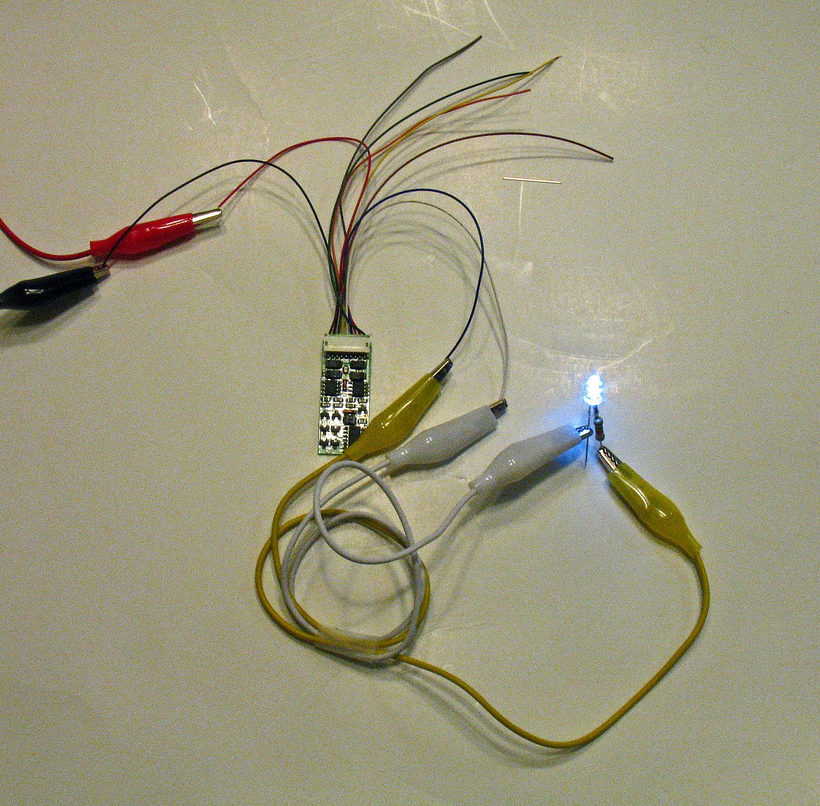
We now have enough knowledge to start connecting LEDs to other things like DCC decoders and signal systems. This can be done in one of two ways, you can use the LED with just a resistor or you can use the 'universal' LED with a resistor and rectifier. There is no drawback to using the simpler LED+resistor for situations, like a DCC decoder, where the polarity of the lighting output is known and constant (users of DCS and TMCC/Legacy will have to determine for themselves whether the light outputs are of constant polarity).

On the other hand, using the universal LED reduces the possibility of error or of accidental damage should the decoder fail the LED can withstand full DCC voltage.

Here's the set up with the 'universal' LED. The decoder is an NCE D13SRJ, which is a basic decoder. Following the DCC color code, the DCC signal is being brought in on the red and black alligator clips; the DCC system driving this is a Lenz Compact, which is my bench DCC system.


The LED is connected to the headlight function output on the blue and white wires coming out of the decoder. Since I do not have a blue alligator clip, I've connected the blue lead via the yellow alligator clip. The blue lead coming out of all decoders is common to all function outputs and it is the POSITIVE lead. By using the universal, rectifier-equipped LED you can ignore the polarity and hook up either wire to either terminal on the rectifier.

Here's the proof in the pudding, the LED lights up:


Here's the set-up with the plain LED+resistor:


And a close-up of the LED hook-up:


In left of the picture above you see the yellow alligator clip connected to the blue lead. The yellow clip is connected, in turn, to the anode of the LED which has the resistor in the lead. If you hook-up this type of LED backwards, you'll likely burn it out; possibly damaging the decoder in the process. I did this once, for this reason I use the rectifier-equipped LEDs, either made by me or those from Evans Designs. The choice is yours, you can do it either way.

A Backdrop for the Cheat River Grade

Over the Thanksgiving weekend I started an ambitious backdrop project - 21+ feet of backdrop for the Cheat River Grade. This backdrop begins before the Tray Run Viaduct and continues until the Kingwood Tunnel. The backdrop will be 42-44 inches at it's deepest. It's supported on 2x4 and 2x3 uprights between the benchwork in the center of the layout. There will be another backdrop on the opposite side, although it will not be as deep.

Here's the first section going up:


Here's a view from the other direction:


Here the second sheet of Masonite, curved appropriately, is in place:


And a view from the other direction:


(Update 12/3) Finished the Masonite (the darker Masonite came from another store):


The joints and screw heads have been spackled. Here's the backside:


Next, I'll design and print a photo backdrop for this site, but that's for another post.

Thursday, November 24, 2011

Track Templates

This story starts a few years back. On one of the layout tours associated with the 2008 O Scale National convention, I was at a huge P48 layout when I spotted some curved track-laying and turnout templates done in bright yellow acrylic. The templates had cutouts for the individual ties as well as gauge lines for the rails. They were marked Canter Rail Services and I thought that it was a neat tool; but since this was a very busy open house, and I did not even know who the host was, I could not ask about them.

After the convention I searched for a "Canter Rail Services", but I could not find any reference to them. Fast forward a couple of years to a O Scale train show in 2010 where I saw some of these templates lying on one of the sales tables. I inquired of the vendor and it was Jim Canter himself. It seems that he was not going to make these any longer and the stock on the table were all that was left. There were two templates for radii that I was using, so I bought those.


The Canter Rail Services templates for 68" (top) and 64" radii


They saw little use in building my railroad as I was still laying-out my curves using a beam compass; and I came to realize that unless I was actually hand-laying track these were less useful than I had first thought. That is, until I was building the part of the Cheat River Grade beyond the Tray Run Viaduct. In that area, I could not use the beam compass to lay out the curves as the pivot point of the beam would have had to be located on the other side of a stud wall. I pressed the little-used Canter templates into service and, although they were not perfect for this task, they worked well enough to make me consider giving up the beam compass.

So as I contemplated laying out the last two mainline curves on the layout I determined to make some more templates to facilitate this task. I decided on using a laser cutting service to cut the templates out of acrylic, just like the originals. However, I would redesign the templates to facilitate laying flex track as I was doing.

The first task was to design the templates in CAD. I used TurboCAD Delux. I've had various versions of TurboCAD since about version 5. It's not the easiest CAD program in the world to use, but it has the virtue of being cheap if you buy an older version. Google Sketch-Up would probably suffice and it's free.

I began by laying out a 72" radius template similar to the Canter ones. The Canter templates have the outer edge 2" longer than the marked radius and the inner edge 2" shorter than the marked radius so that when two templates of different radii are butted adjacent to one another the track center spacing is set for the nominal 4" for O scale. I followed suit on my 72' radius template.

I did not need the slots for the individual ties and cutting them on the laser cutter would be very expensive. What I did need was a slot down the middle, on the track radius, to mark the track center line. I layed-out a 0.080 inch slot down the center of the template on the 72" radius. The 80 thousandths slot would accommodate a pencil, pen or a Sharpie marker. In the corners of the Canter templates are four holes to allow the template to be fastened down; I replicated these holes. I sized the template to fit one of the standard sized sheets of acrylic that the laser cutting service provided. The result is shown below.


I sent this design to the laser cutting service to obtain a price. The cost of cutting this template was reasonable, less than the cost of the original Canter templates. That caused me to think about the large two-turn helix in the center of my layout.

I had been contemplating how I was going to cut each segment of the sub roadbed of this large spiral. I had wanted to have the sections cut on a CNC router, but I could not find such a service near enough to where I live to make it economically feasible; and shipping 20 or so sections made of 3/4" plywood would be very expensive. I could make a template and cut the sections out myself. However, besides being very time-consuming, I did not think that I could make a template accurate enough that it would result in a accurate two-turn helix.

Laser cutting the template would remove that last consideration. There are two tracks on my helix so I had to lay out a double-wide template with center lines for two tracks. I increased the track center-to-center distance to 4.5 inches to allow for the boiler swing of the articulated locomotives that I will be running. While I was at it, I increased the width of the template to 9.5 inches, 2.5 inches beyond the outer track center line and 2.5 inches inside the inner track center line - also for boiler swing. I sized the template to fit the short dimension of a 4x8 sheet of plywood to maximize the number of segments that I could cut from a single sheet.

Now, I would have to buy a larger sheet of acrylic at the laser cutter's so I decided to design one more template to fill up the sheet. I had 64" & 68" Canter templates, I had designed a 72" radius template, so I designed a 60" radius one for a curve that I had. That would give me a complete set from 60" to 72" plus the template for the helix. Since I was now cutting a larger sheet of plastic, there was no reason to make the 60" template the same size as the others and I made this one considerably longer. Here's the drawing for all three of the templates that I had laser cut:


These are, from the top, the double track helix template, the 60" radius template and the 72" radius template.

As this was my first foray into designing for laser cutting I was anxious to see how these templates came out. The three templates as they came from the cutter are show below.


I was impressed with the finish on the cut edges, they are almost polished by the laser. In the next picture, I have fitted the 72" and 60" to the 64" and 68" Canter templates; they fit together perfectly.


I had removed the protective paper from the 72" template before I realized that it would photograph poorly without it. Today I bought some lumber to begin using the helix template to cut the sections for the helix. Hopefully, I'll be ready to begin building the helix by Christmas.

Sunday, November 20, 2011

Fun with LEDs II

This is a continuation of the original post "Fun with LEDs"

The original post was linked to a forum and I solicited and received feedback to simplify the photos of a simple LED setup, that is, without the alligator clips. So I put on my thinking cap and tried to come up with the simplest way to light up an LED. Here's what I came up with.

Take an LED (color of your choice), a resistor (any value around 300 ohms) and a 9 volt battery. Then do the following:

1) Cut the anode of the LED (positive terminal) off to about 1/4 to 3/8 inch long.
2) Now cut off one wire from the resistor to about 1/4 to 3/8 inch.
3) Overlap and solder the cut end of the resistor to the cut anode.
4) Cut the other wire coming out of the resistor to the same length as the cathode (the outer wire coming out of the LED).

What you have now should look like this:


Your resistor might not match the one that you see here; yours may be one of the little 'dog bones' rather than the old school resistor you see in the photo.

Now:

5) Spread the cathode and anode as you see in the picture.
6) Wedge LED into the terminals of the 9 volt battery. BE SURE TO PLACE THE ANODE ON THE POSITIVE TERMINAL AND THE CATHODE ON THE NEGATIVE TERMINAL OF THE BATTERY!

You should now have a lit-up LED atop the battery like this:


The posters in the forum made a big deal about determining the proper value for the resistor. The calculated value for a resistor for 9V is 330 ohms; but if you know the resistor color code, the resistor that I used is 220 ohms (Red-Red-Brown). This resistor should be allowing 40 ma to pass; that's well above the published recommendations for most LEDs. It just illustrates that there is some latitude in the current that an LED can handle, but any time you go above 25 ma you are taking a risk.

Now that you can light-up an LED using DC of a known polarity and voltage what do you do if you want to light an LED with AC or DCC (DCC is a form of AC)? Or if you want to light an LED with DC that can change polarity each time direction is changed like an LED mounted in a caboose, passenger car or locomotive?

The simplest way is to add a rectifier to convert the AC, DCC or reversing DC to a constant and unchanging polarity DC for the LED. The process of "rectification" converts an AC signal which changes polarity many times a second to DC. Today's rectifiers are devices that combine four diodes in a 'bridge' arrangement that convert AC to DC. They will also take DC which switches polarity and convert it to constant polarity.

Bridge rectifiers come in a variety of shapes, sizes and capacity; see the photo below:


The little guy on the left is a 1 amp rectifier in a 'mini-dip' package; it's the one that we will be using. 1 amp is more than is necessary, but it's about as small as rectifiers come. Next to it is a button with four leads; this is a 1.4 amp bridge rectifier. This size/form factor could be used for our next design as well. To illustrate the other extreme in rectifiers, the rectifier on the right is a 35 amp unit used in the larger power supplies.

Here's a close up of the mini-dip rectifier:


You'll notice the two pins marked with a 'squiggle' (or tilde, ~ , if you prefer). These are the pins where the AC, DCC, or switching DC are applied. It does not matter which wire is applied to which pin. On the far side of the device, are two pins marked with a '-' and a '+'. These are the pins where the rectified, constant DC comes out.

This rectifier is All Electronics part number #FWB-11 (35 cents as of this writing). Other similar parts are: Digikey DF01MDI-ND (49 cents)and DB102-BPMS-ND (73 cents).

The first step in preparing the rectifier for use with the LED is to flatten out the pins as shown in the following picture:


Now take the diode/resistor assembly that you made above and solder the resistor side to the positive terminal and the cathode side to the negative terminal. What you wind up with is an assembly that looks like this:


If you have sharp eyes, you'll notice two things about this set-up. First I've changed the resistor to 1500 Ohms (Brown-Green-Red). Second, my soldering skills are poor; therefore if I can do it you can too.

I've changed the resistor because I'm going to run this circuit off of a higher voltage and I did not want to blow out the LED. 1500 Ohms is a lot better value to use for all-around use at track voltage or at DCC voltages. Again this is not critical, any value above about 680 Ohms should work. Ordinarily, I'd cover this circuit with heat-shrink tubing to insulate and protect the circuit, but I've left it exposed to show how it's constructed.

In the next photo, I'm running this circuit from 12V DC as you would if this were running off of DC track voltage:


To demonstrate that the rectifier will take care of polarity changes, in the next photo I've reversed the polarity of the incoming current:


You can see that the red and black wires have been interchanged. In the next photo, the circuit is running on DCC track output.


If you wanted to, you could replace the single LED with a series string of 2 or more LEDs, as was done in section 1. Since rectifiers are relatively expensive, this makes sense to do. Light an entire passenger car or structure from a single rectifier/resistor set-up.

Evans Designs makes a similar unit, with the heat-shrink tubing attached, in three sizes and several colors for $3.25 each. The Evans Designs LEDs have wire between the rectifier and the LED and wires for the incoming current; this makes them convenient to install. Evans Designs Universal LEDs Here's a photo a 3mm size LED running on 12V below:

From 2-Rail O Scale Railroading


Although these are somewhat more expensive than rolling your own, I use them extensively in locomotives and rolling stock.

To be continued...